SECTION 4: INSTALLATION AIR N ARC
®
200 SERIES ALL-IN-ONE POWER SYSTEM
®
PAGE - 38 090019-OP_r0
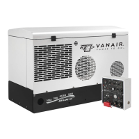
2. Using a proper hoist, lift and place the unit in a
preliminary position on the service body of
the vehicle so that access is easily attained,
the control trunk line and all other
connections will reach the unit, and there is
enough space surrounding the mounting
area for cooling purposes. Refer to Figure 4-
4 for lifting bail location.
3. Route the control trunk-line through the
grommeted opening. Connect the ½” air line
via the JIC fitting on the end of the air tank,
and connect and secure the weather proof
connectors. The plugs are all differentiated
to ensure that they cannot be mis-
connected.
4. Connect and clamp the fuel line to the in-line
fuel filter located on the engine near the left
valve cover as you are looking at the motor,
if using truck tank.
5. Leaving the unit in the preliminary position,
connect the ground cable to the unit battery,
and check all fluid levels (NOTE: vehicle
should be on a level surface in order to get
accurate fluid level checks).
6. Turn the Ignition switch on the control panel to
“ON”. While the ON sequence is initiated,
check that the fuel pump is energized. Wait
3-5 seconds for the fuel pump to prime the
fuel system. The unit will start more quickly if
the fuel pump is manually pre-energized to
prime the fuel system. Start and run the unit
for a few minutes, then turn the machine off.
Check fuel connections for leaks, verify all
connections, and replace access panel and
close hood.
7. Move the unit into its final location for
mounting, while positioning the control trunk
line and all other connections.
8. Bolt the machine down with four ½” bolts
inserted up from the bottom through the four
mounting bolt holes of the base frame. See
Section 4.5, Installation and Dimensions
Diagram, Part 1 and Part 2.
9. Start the unit and fully test all functions. Warm
the unit to full operating temperature. After
the unit has cooled, check all fluid levels and
add as needed.
Figure 4-4: Lifting Bail Location
CAUTION
Lift the machine package in accordance
within the safety guidelines given in
Section 1.7.1, Falling Unit Can Cause
Injury.
NOTE
For guidance on machine start-up
procedure and control panel functions,
consult Section 5, Operation.
NOTE
It is recommended that the machine be
mounted on a vibration isolating material
such as 1/4” neoprene rubber pads.
Isolating Dampeners (Part Number
PR93969) are available by calling the
Vanair
®
Customer Service Department.