Series 65 INSTALLATION
963283EA Edition 2019-05-03 25/
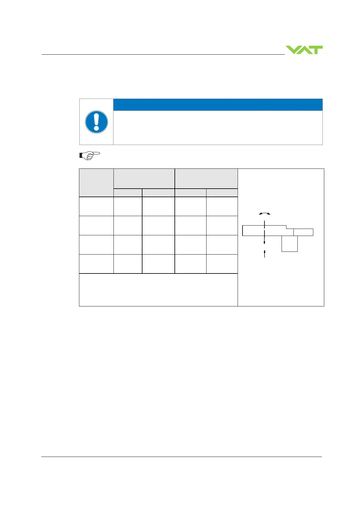
4.2.7 Admissible forces
Force at valve body
Forces from evacuating the system, from the weight of other components, and from
baking can lead to deformation and malfunctioning of the valve.
Do not higher force the valve body as specified.
The following forces are admissible.
Valve size
Axial tensile or
compressive force
«F
A
»
Bending moment «M»
N lb. Nm lbf.
DN100 / 4“
(65340 - . . . .
- . . . . )
1000 220 40 30
DN160 / 6“
(65344 - . . . .
- . . . . )
2000 440 80 60
DN200 / 8“
(65346 - . . . .
- . . . . )
2000 440 80 60
DN250 / 10“
(65348 - . . . .
- . . . . )
2500 550 100 75
For a combination of both forces (F
A
and M) the values are
invalid.
Verify that the depth of the mounting screws is min. 1 x thread
diameter.
Please contact VAT for more information.
4.2.8 Requirements to sensor connection
To achieve fast and accurate pressure control a fast sensor response is required. Sensor response time:
< 50ms. The sensor is normally connected to the chamber by a pipe. To maintain that the response time
is not degraded by this connection it needs to meet the following requirements:
•
Inner diameter of connection pipe: > = 10 mm
•
Length of connection pipe: < = 300 mm
These conductance guidelines must include all valves and limiting orifices that may also be present. Make
also sure that there is no obstruction in front of sensor connection port inside the chamber. The sensor
should also be mounted free of mechanical shock and vibration. Dynamic stray magnetic fields may
introduce noise to sensor output and should be avoided or shielded.
F
A
M

 Loading...


