Pax-i3D Smart(PHT-30LFO) Installation Manual
22
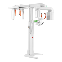
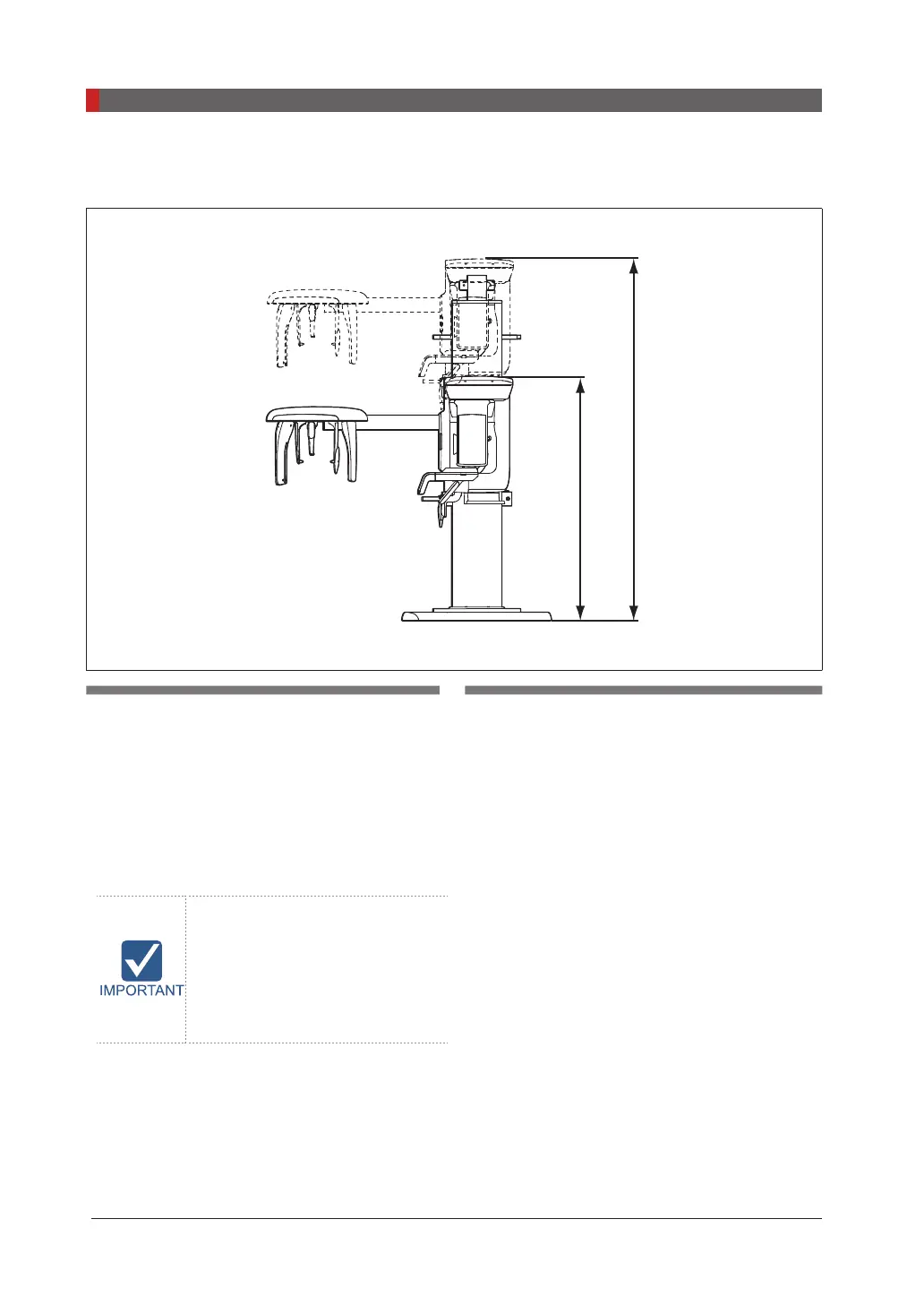
2 Choosing an Installation Site
Ceiling Height: ≥2,600mm/103”
1536 mm
2336 mm
Minimum space required:
●
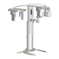
With Cephalometric unit:
2,500mm(L)
x 2,500mm(W) x 2,600mm(H)/98.4"(L) x
98.4"(W) x 103"(H)
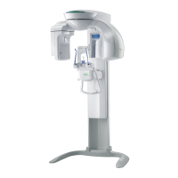
●
Without Cephalometric unit:
2,500mm(L)
x 1,700mm(W) x 2,600mm(H)/98.4"(L) x
67"(W) x 103"(H)
If the ceiling height is less then
2436mm(=Column Max. height +
100mm), refer to
the Appendix
C. Limiting the Column Height
lower the column Max. height.
The system is normally installed beside a wall,
and the operator uses the system on the left.
Lead thickness: ≥1 mm
Width of the entrance:
The door of the X-Ray room should have a
clearance of more than 800 mm (31.5”) wide.
Floor area:
The oor of the X-Ray room must be stable
and level for system balance.
The oor must be able to support a minimum
weight of 500 kg/
m
2
(110 lbs/
feet
2
).
Protection against radiation
● To protect against radiation hazards, follow all
federal and municipal requirements.
● During exposure, the operator should follow
applicable radiation shielding requirements
and remain at least 2m (7’) from the source of
the radiation.
● Maintain visible contact with the patient and
a clear view of indicators such as the warning
lamp and imaging status on the PC.
 Loading...