Pax-i3D Smart(PHT-30LFO) Installation Manual
54
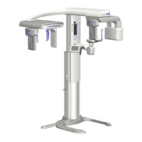
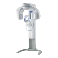
4 Installing the Equipment: Floor Standing (Optional)
4.3
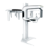
Connecting the Cables to the Equipment
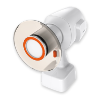
OPTIC2(SCAN CEPH)
Part No.: 22
OPTIC1(PANO/CT)
Part No.: 22
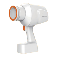
Exposure Switch
Part No.: 2
1.
Connect the cables in the back of the column
as shown in the gure.
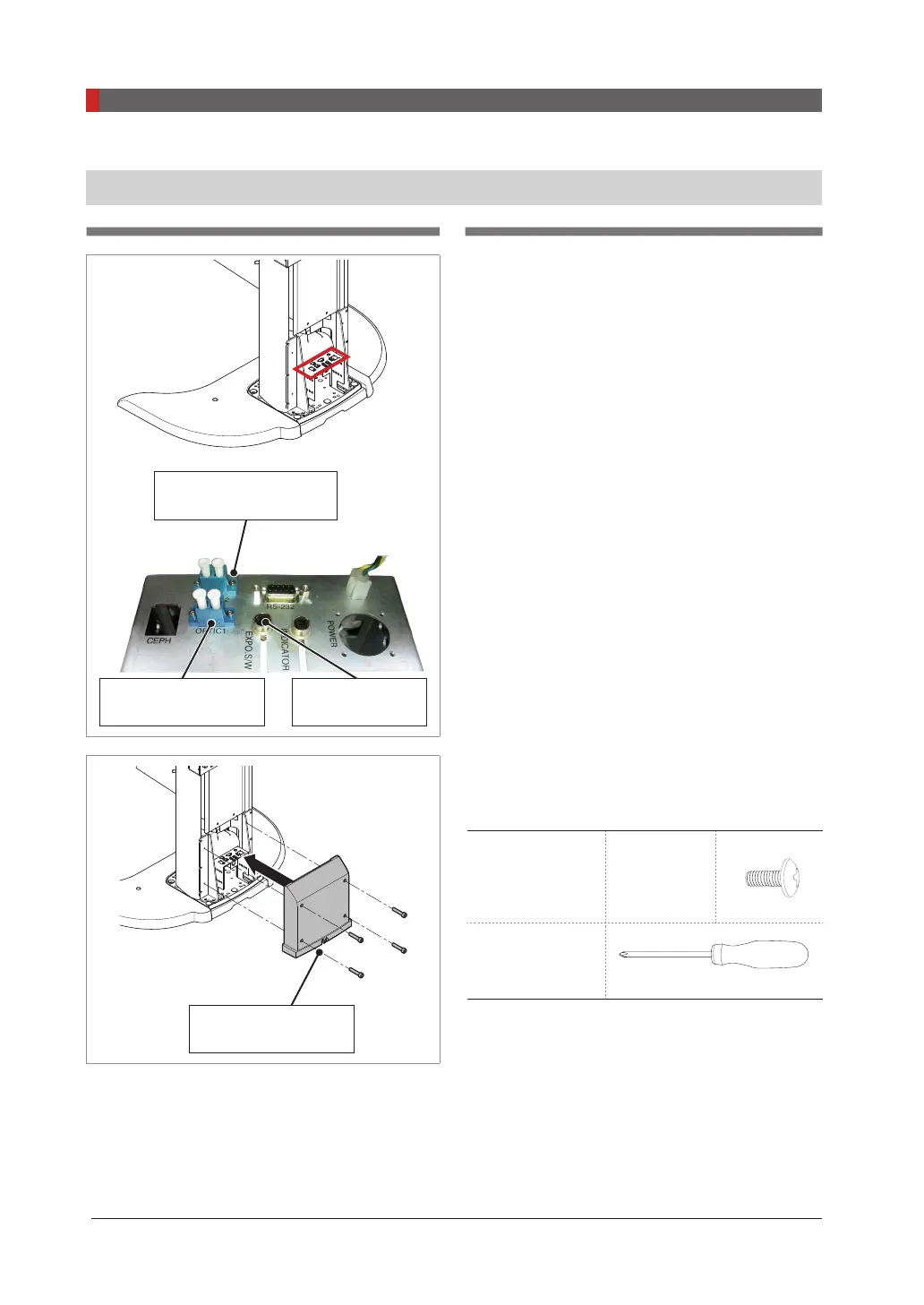
COLUMN BACK
COVER hole
2.
Assemble the COLUMN BACK COVER with
four truss bolts. Ensure the cables go through
the COLUMN BACK COVER holes.
Truss bolts
M4 x 8
Part No.: 27
4 pcs
Cross head
screw driver with
magnetic tip
 Loading...