Do you have a question about the Vatech PaX-i Plus and is the answer not in the manual?
Covers manufacturer's liability and customer's site preparation duties.
Explains symbols and warnings used in the manual for user and equipment safety.
Specifies installation location requirements and crucial safety warnings about X-ray radiation.
Detailed list of symbols with descriptions and their locations on the equipment.
Lists international standards and regulations the equipment complies with.
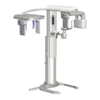
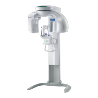
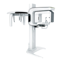
Guidelines for selecting an appropriate installation location, ensuring visibility and stability.
Detailed electrical installation specifications and mandatory requirements for safe operation.
Specifies operating and storage conditions for temperature, humidity, and atmospheric pressure.
Presents three options for installing the Exposure Switch, with a preferred method.
Lists all necessary tools for installing the PaX-i Plus / Insight system.
Procedure to visually inspect packages for damage using impact and tilt indicators before opening.
Details on how to unpack the main box containing the equipment and accessories.
Instructions for verifying all parts and accessories are present using layout diagrams and lists.
Steps for safely unloading the main unit from its packaging, emphasizing stability.
Steps for temporarily attaching the base unit to the column using bolts.
Procedure for attaching wall and column brackets to the unit using specific bolts.
Steps to level the equipment using a spirit level and adjusting screws for stability.
General advice on planning and studying the installation environment for wall mounting.
Steps to place an alignment plate and mark anchor bolt holes on the floor.
Instructions for drilling holes in the floor and securing anchor bolts.
Procedure for placing the equipment on anchor bolts and loosely tightening nuts.
Steps for assembling the base cover using truss bolts and base caps.
Procedure to insert chinrest, bite blocks, temple supports, and cap ear rods.
Steps for installing UP/DOWN switch holder and exposure switch holder.
Illustrates the connection diagram for the PC, imaging system, and peripherals.
Specifies the minimum hardware and software requirements for the PC.
Instructions to disable Windows Defender for optimal software performance.
Steps for installing internal peripherals and connecting necessary cables to the PC.
Pre-configuration checks and steps to verify and configure PC BIOS settings.
Procedure to disable Windows Firewall to prevent interference with imaging data transmission.
Steps to disable screen saver and configure power options to prevent abnormal operation.
Instructions to exclude specific folders from virus scans to prevent software conflicts.
Pre-installation checks for software, including emergency stop, irrelevant programs, and virus scans.
Step-by-step guide for installing the main software package from the CD.
Instructions for installing DirectX and frame grabber/virtual serial drivers.
Guidance on configuring user-specific settings based on the installed viewer program.
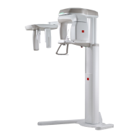
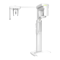
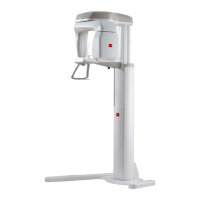
Provides detailed dimensions, weight, and movement specifications for the equipment.
Lists electrical requirements including voltage, frequency, power rating, and accuracy.
Specifies the operating and storage environmental conditions like temperature and humidity.
Requirements and block diagram for installing warning lamps and door interlock switches.
Guidelines for installing the emergency stop switch, including height and cable requirements.
Details on how to check and configure PC BIOS settings for the HP Z440 model.
A checklist for general information and customer/dealer details prior to installation.
| Brand | Vatech |
|---|---|
| Model | PaX-i Plus |
| Category | Dental equipment |
| Language | English |