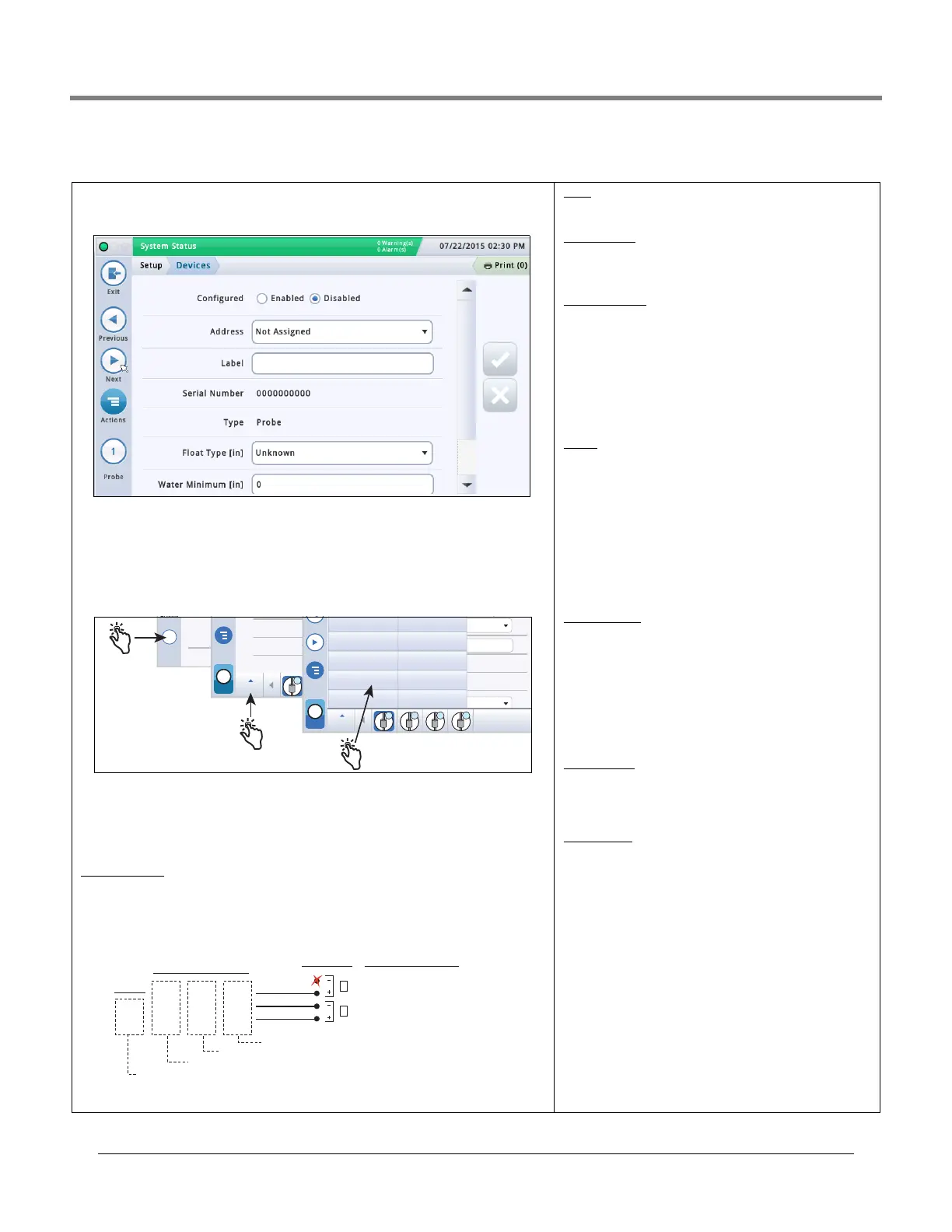
Initial Setup Of The Console Using Workflow Wizard Setup>Devices
19
Setup>Devices
The Setup>Device screens let you configure each of the monitored devices that is con-
nected to the console (probes, sensors, relays, external inputs) and (LVDIM/MDIM modules
- TLS-450PLUS only).
Relay will display the following possible address codes in the
Address Field: B1:S1:X , where X = 14 (relay connector
input 1) or 15 (relay connector input 2).
External Input will display the following possible address
codes in the Address Field: B1:S1:X , where X = 12 (Ext.
Input connector input 1) or 13 (Ext. Input connector input 2).
TLS-450PLUS Consoles
Probes/Sensors connected to the console will display the
following possible address ports in the Address Field:
B1:Sx:X, where Sx is the slot in which the USM module is
installed (from 1 to 4) and X is the connector input to which
the device is attached (from 1 to 16). NOTE: 3-wire sensors
require three connector inputs (2 ‘+’ channels and 1’ – ‘
channel) so each 3-wire sensor takes up two of the available
intrinsically safe ports and has two addresses (Address field
and Address 2 field (see 3-Wire Sensor Addresses Example
illustration above).
Relays connected to the I/O module will display the follow-
ing possible address codes in the Address Field: B1:Sx:X,
where Sx is the slot in which the I/O module is installed
(from 1 to 4) and X is the connector input to which the device
is attached (from 5 to 9). Note: The relay address B1:S7:1
refers to the single input Power Bay relay which, if used,
would connect to the site’s Overfill Alarm.
Relays connected to a 10 AMP Controller module will display
the following possible address codes in the Address Field:
B1:S4x:X, where S4 is the only slot in which the 10 AMP Con-
troller module is installed and X is the connector input to
which the device is attached (from 1 to 6).
External Inputs
connected to the I/O module will display the
following possible address codes in the Address Field:
B1:Sx:X, where Sx is the slot in which the I/O module is
installed (from 1 to 4) and X is the connector input to which
the device is attached (from 1 to 4 and 10 to 14).
External inputs connected to a 10 AMP Controller module will
display the following possible address codes in the Address
Field: B1:S4x:X, where S4 is the only slot in which the 10
AMP Controller module is installed and X is the connector
input to which the device is attached (from 7 to 12).
LVDIM inputs
connected to the console will display the fol-
lowing possible address codes in the Address Field: B1:Sx:X,
where Sx is the slot in which the LVDIM module is installed
(from 1 to 4) and X is the connector input to which the device
is attached (from 1 to 12).
MDIM inputs connected to the console will display the fol-
lowing possible address codes in the Address Field: B1:Sx:X,
where Sx is the slot in which the MDIM module is installed
(from 1 to 4) and X is the connector input to which the device
is attached (from 1 to 12).
Selecting A Device Type
Initially the first device type to be displayed in Workflow Wizard setup is Probe 1. To select
another probe, touch the probe 1 button on the lower left of the screen and select the
desired probe from the icon list along the bottom of the probe device screen. To select
another device type, use the touch sequence shown in the illustration below to view the
device matrix, then touch the desired device type button to open that device’s setup screen.
Selecting A Device Address
IMPORTANT! You must know to which console connector a device is wired to select the cor-
rect address for that device. Some general rules discussed below concern device
addresses.
TLS4 Consoles
Probes/Sensors connected to the console will display the following address code in the
Address Field: B1:S2:X , where x is the connector input to which the device is attached
(from 1 to 16). NOTE: 3-wire sensors require three connector inputs (2 ‘+’ channels and 1 ’
– ‘ channel) so each 3-wire sensor takes up two of the available intrinsically safe ports and
uses two addresses (see 2- and 3-wire connection examples below):
Actions
1
Probe
Water
Next
Actions
1
Probe
Probe
1 2 3 4
Serial Number
Type
Float Type [inch
Previous
Next
Actions
1
Probe
Probe
1 2 3 4
Address
Label
Serial Number
Type
Float Type [inch
External Input
Liquid Sensor
Type A Sensor
Type B Sensor
Line Pressure Sensor
LVDIM
ATM Pressure Sensor
Vapor Pressure Sensor
Ground Water Sensor
Groundwater Sensor
Example Port Address
Selections
Console
Connections
3-Wire
Sensors
All
2-Wire
Sensors
B1:S1:1 Address Field Selection
B1:S1:2 Address 2 Field Selection
Vapor Sensor
GRN
WHT
RED
GRN
WHT
BLK
RED
BLK
WHT
BLK
WHT*
4Site Pan/Sump (Type B) - Standard and Optical
1
2
Not used with
3-wire sensor
*Red wire instead of White for:
• Interstitial Sensor - Steel Tanks (794380-4X0)
• CSTP Liquid Switch
• Position Sensitive Interstitial Sensor - Steel Tanks (794380-333)