74
9 Set up with the display and adjustment module
VEGAPULS 6X • Two-wire 4 … 20 mA/HART
66190-EN-221107
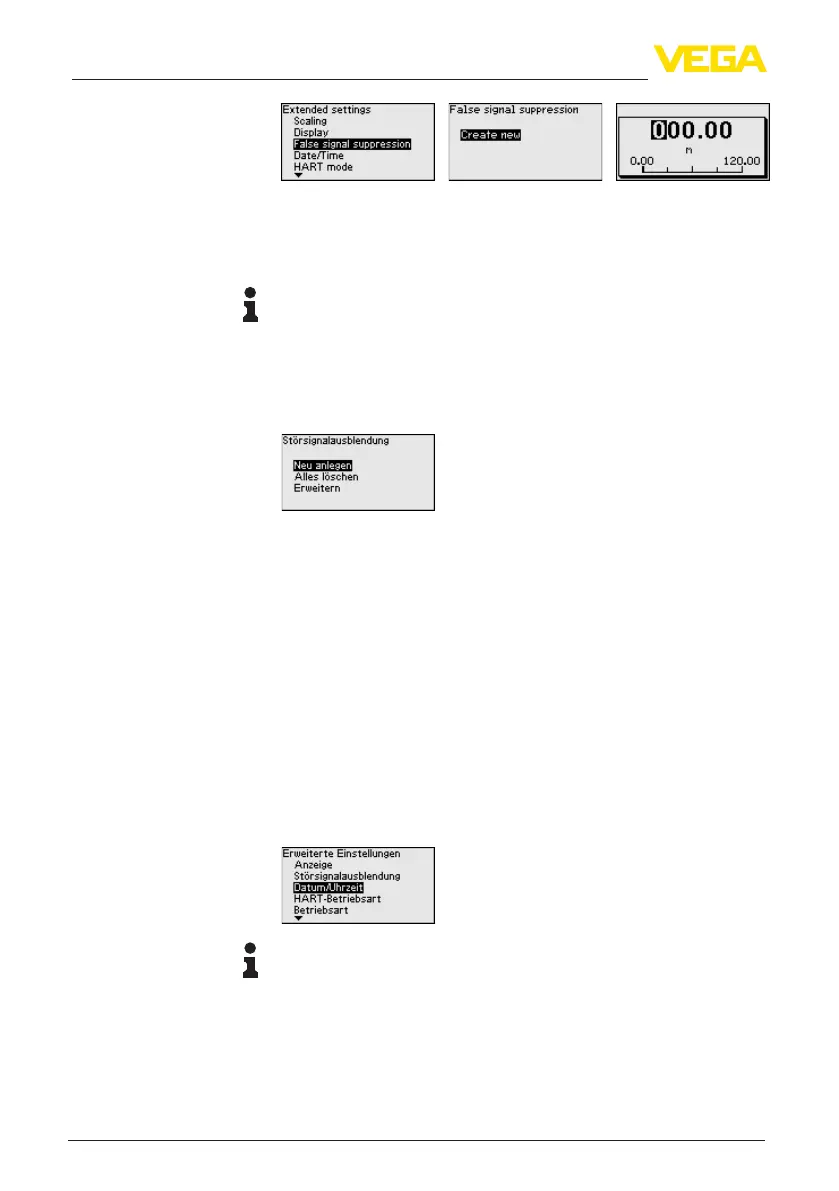
2. Conrm3-timeswith[OK] and enter the actual distance from the
sensor to the product surface.
3. All interfering signals in this range are detected by the sensor and
storedafterbeingconrmedwith[OK].
Note:
Check the distance to the medium surface, because if an incorrect
(too large) value is entered, the existing level will be saved as a false
signal. The level would then no longer be detectable in this area.
If a false signal suppression has already been saved in the sensor,
the following menu window appears when selecting " False signal
suppression":
Delete all:
An false signal suppression that has already been created is com-
pletely deleted.
→Thisisusefuliftheappliedfalsesignalsuppressionnolonger
matches the metrological conditions of the vessel.
Extend:
A false signal suppression that has already been created is extended.
The distance to the medium surface of the created false signal sup-
pression is displayed. This value can now be changed and the false
signal suppression can be extended to this area.
→Thisisusefulifafalsesignalsuppressionwascarriedoutwhenthe
level was too high and thus not all false signals could be detected.
In this menu item, the internal clock of the sensor is set to the desired
time.
Note:
The device is set to CET (Central European Time) at the factory.
In this menu item you specify the HART mode and enter the address
for multidrop mode.
HART address 0:
In the menu item " Output mode" the " Analogue current output" is
displayed and a 4 … 20 mA signal output.
Date/Time
HART mode





 To Next Page