Table 1-2
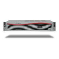
Appliance control panel
DescriptionComponentNumber
The system ID LED identifies the system for
maintenance.
System ID with integrated
LED
1
When the NMI button is depressed, the appliance
goes into a halt state, and issues a non-maskable
interrupt (NMI). This feature is useful when you
perform diagnostics for a given issue where a memory
dump is necessary to help determine the cause of
the problem. To prevent an inadvertent system halt,
the NMI button is located behind the front control
panel faceplate. It is only accessible with the use of
a small tipped tool, such
NMI button (recessed, a
tool is required for use)
2
NIC-1 represents the network interface controller 1.
When network links are detected on the controllers,
the LEDs are activated and remain on. The LEDs
blink when network activity occurs. The amount of
network activity determines the rate of blinking.
NIC-1 Activity LED3
The System Cold Reset button restarts and
re-initializes the appliance.
System Cold Reset
Button (recessed, a tool
is required for use on
non-storage models)
4
The System Status LED uses the colors green and
amber to display the health of the appliance.
System Status LED5
The Power/Sleep button turns off the appliance or
turns on the appliance.
Power/Sleep button with
integrated LED
6
The drive activity LED indicates drive activity from
the on-board hard disk controllers.
Hard drive Activity LED7
NIC-2 represents the network interface controller 2.
When network links are detected on the controllers,
the LEDs are activated and remain on. The LEDs
blink when network activity occurs. The amount of
network activity determines the rate of blinking.
NIC-2 Activity LED8
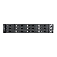
Appliance rear panel
The rear panel of the appliance contains several default ports that are embedded.
Three PCIe riser assemblies support various configurations.
9Hardware overview
Appliance rear panel
 Loading...