System Operation and Maintenance 48
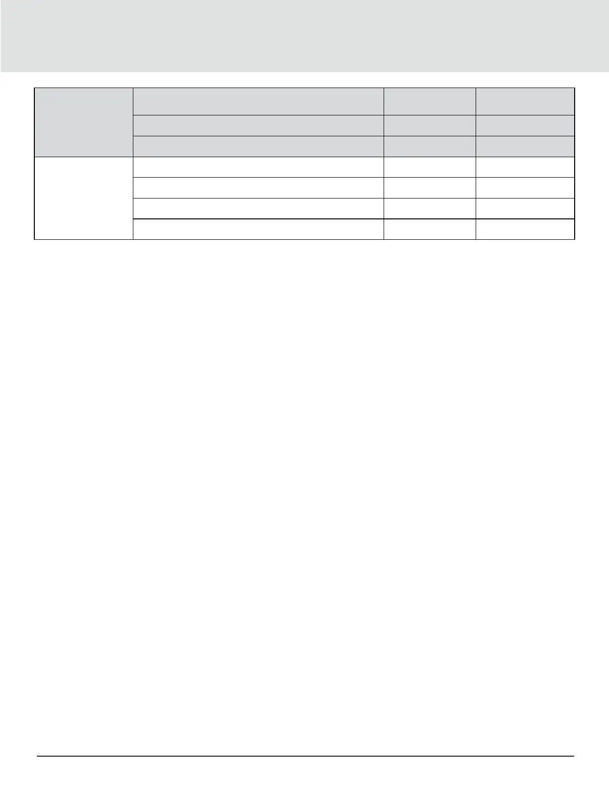
Fan
Check whether the rotating blades will cause friction on
the nearby metal parts
Listen to whether there is abnormal noise
Observe whether there is obvious vibration in the fan
Control system
Examine fuse and circuit breaker
Check and fasten the circuit connector
Check the contactor pull-on status
Check the control program
5.3. Self-Diagnostic System
The controller provides the diagnostic function of manually opening and closing components, which is used to self-test the
state of the functional components of the system.
5.4. Check the Electrical Connections and Maintenance
Following are the electrical connections to make visual inspection and treatment:
1. Conduct an overall electrical insulation test: Find out the unqualified contacts and handle them carefully. Note to
disconnect the fuses or MCBs of the control part during the test before the high voltage should damage the control
components.
2. Check the contactors before power-On and ensure the contactors can act freely without obstruction.
3. Clean the electric and control elements of dust with a brush or dry compressed air.
4. Check the closing of contactors for arcs or signs of burning. Replace the contactor if necessary.
5. Fasten all the electrical connection terminals.
6. Check whether the sockets and plugs are in good condition. Replace those damaged ones.
7. If the power cables are damaged, to avoid further damage, the cables must be replaced by professional personnel.
5.5. Appearance Inspection and Maintenance of Controller Components
A control section to make visual inspection of the following entries, and a simple function test process:
1. Visually inspect the power transformers and isolation transformers and test the output voltage of the indoor unit and
outdoor unit.
2. Check whether there are no signs of aging on the control interface board, control board, temperature, and humidity sensor
board.
3. Clean the electrical control elements and control board of dust and dirt with brush and electronic dust removing agent.
4. Check and fasten the I/O ports at the control interface board, including the connection between control board and control
interface board, as well as between the temperature/humidity sensor board and the interface board.
5. Check the connection between the user terminals ( 37#, 38#) and the control interface board.
6. Check the output connection between the control interface board and various contactors and water valves, and the input
connection between control interface board and fan overload protector, and replace the component if it is in poor condition
or is faulty.
7. Check and replace electrical components that are faulty, such as control fuses (or MCBs) and control boards.
8. Check the specification and aging condition of the control cable and power cable between the indoor unit and the outdoor
unit and replace the cables if necessary.