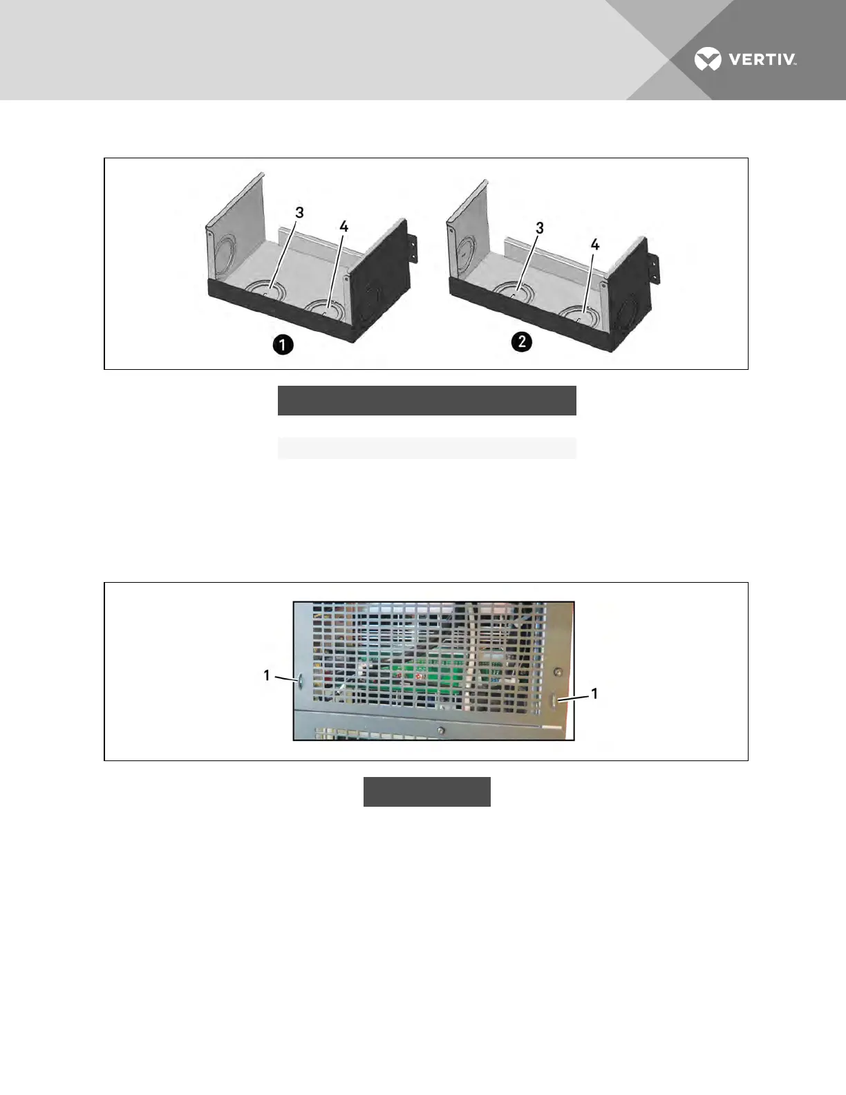
Figure 3.13 Knockouts in Units without Transformer
ITEM DESCRIPTION ITEM DESCRIPTION
1 16-bay, no transformer 3 Output-cable knockout
2 10-bay, no transformer 4 Input-cable knockout
2. Connect the cables to the corresponding terminal of the power input and output terminals.
3. Using a 13-mm (1/2-in.) torque wrench, tighten the screws to 4.52Nm (40in-lb).
4. Respectively, secure the conduit of the input/output cables through the cable bridges on the
rear panel of the UPS, see Figure 3.14 below.
Figure 3.14 Secure cables on cable bridges
ITEM DESCRIPTION
1 Cable bridge
The connection methods for single-phase and the 3-phase input modes are shown in Figure 3.15 on the
facing page and Figure 3.16 on the facing page, respectively. Installation of the factory-provided copper
bar is essential in the single-phase input mode. The copper busbar is in the accessory bag included with
the UPS.
Vertiv | Liebert® APS™ Installer/User Guide | 34