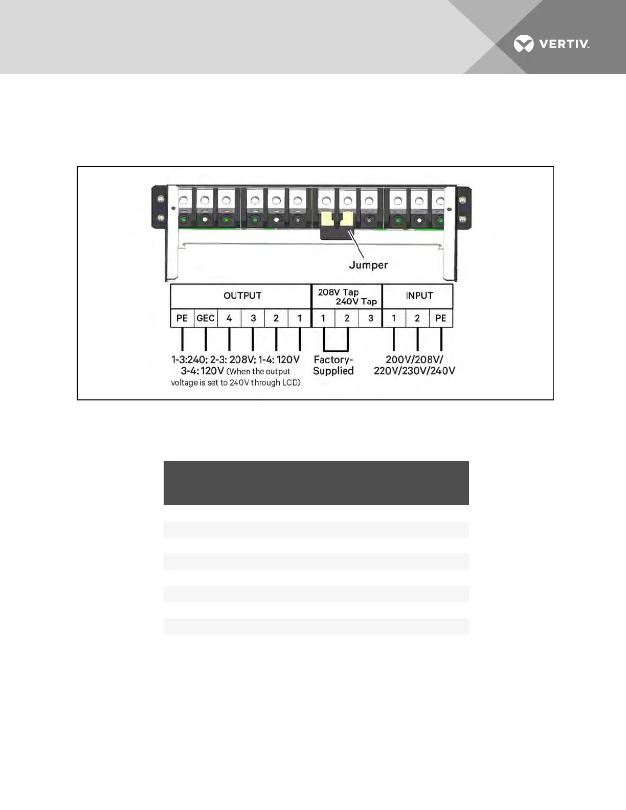
2. Connect the cable to the corresponding terminal of the power input and output terminals as
shown in Figure 3.21 below.
3. Using a torque wrench, tighten the screws to 12.43Nm (110in-lb).
Figure 3.21 Connection method
Refer to Table 3.6 on page37 for configuring the output cable. For standard voltages, make the
connections shown in Table 3.8 on the facing page.
SYSTEM VOLTAGE SYSTEM NOMINAL FREQUENCY
INPUT TERMINAL BLOCK
1 2 PE
200 60 L1 L2 GND
208 60 L1 L2 GND
220 60 L1 L2 GND
230 60 L1 L2 GND
240 60 L1 L2 GND
200 50 L N PE
220 50 L N PE
230 50 L N PE
240 50 L N PE
Table 3.7 Key to Figure 3.21 above UPS input wiring
Vertiv | Liebert® APS™ Installer/User Guide | 40