Vertiv | Liebert® CRV4 | User Manual 92
System Operation and Maintenance
8.7. General Maintenance for the Electrode Humidier
If the unit is equipped with electrodes for humidication, it should be regularly maintained.
8.7.1. Operating Guidelines for the Electrode Humidier
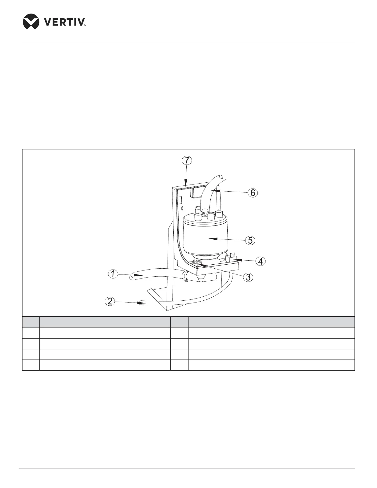
The electrode humidier kit consists of a bracket (including water pressure components such as inlet, outlet
solenoid valves), humidier canister, humidication control board CPY (located in a metal box close to the
humidier), power frequency transformer, high frequency current transformer, contactor, relay, water-in pipe,
drain pipe, relay socket and steam pipe as shown in Figure 8-3.
No. Description No. Description
1 Drain Pipe 5 Humidier canister
2 Water in pipe 6 Steam pipe
3 Outlet solenoid valve 7 Bracket
4 Inlet solenoid valve
Figure 8-3 Electrode Humidier
The micro-controller calculates if humidication is required based on the humidity and temperature values
from the temperature/humidity sensor. If a call for humidication is registered, the micro-controller will send
a humidication signal to the humidication control board and provide 24 V power supply to it. Then the
humidication control board will start the humidication process. The Humidication control board adopts
On/ O operation mode, and controls the humidication operation based on the programmed procedure. The
humidication control board is located in a metal box close to the humidier and its interfaces are shown in
Figure 8-4.