Vertiv | Liebert® CRV4 | User Manual 14
Mechanical Installation
The following points should be considered before checking out the overall layout diagram
• : Factory piping
•
: Field piping (by technical personnel)
• Components (marked with *) are not supplied by Vertiv and are recommended for proper circuit operation
& maintenance.
• Additional components (marked with +) are required when the equivalent length exceeds 30 m.
3.1.2. System Installation Mode
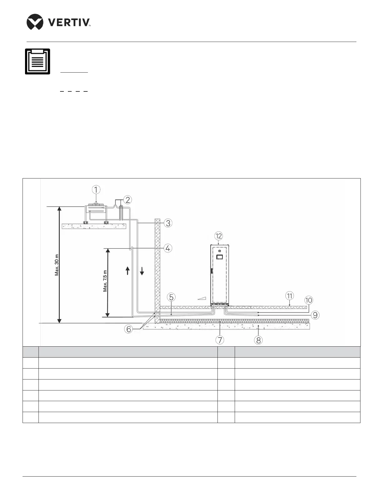
The installation modes of the Liebert® CRV4 series unit are shown in Figure 3-2 and Figure 3-3.
No. Description No. Description
1 Outdoor unit 7 Heat insulation oor
2 Back bend
(must be higher than the highest copper pipe of the condenser) 8 Floor
3 Liquid line
(avoid exposure to direct sunlight) 9 Condensed water out
4 Trap 10 Humidier water in
5 Slope discharge 11 Raised oor
6 Sealed 12 Indoor unit
Figure 3-2 The Outdoor Unit is Placed Higher than the Compressors during Installation