Vertiv | Liebert CRV+ | User Manual 42
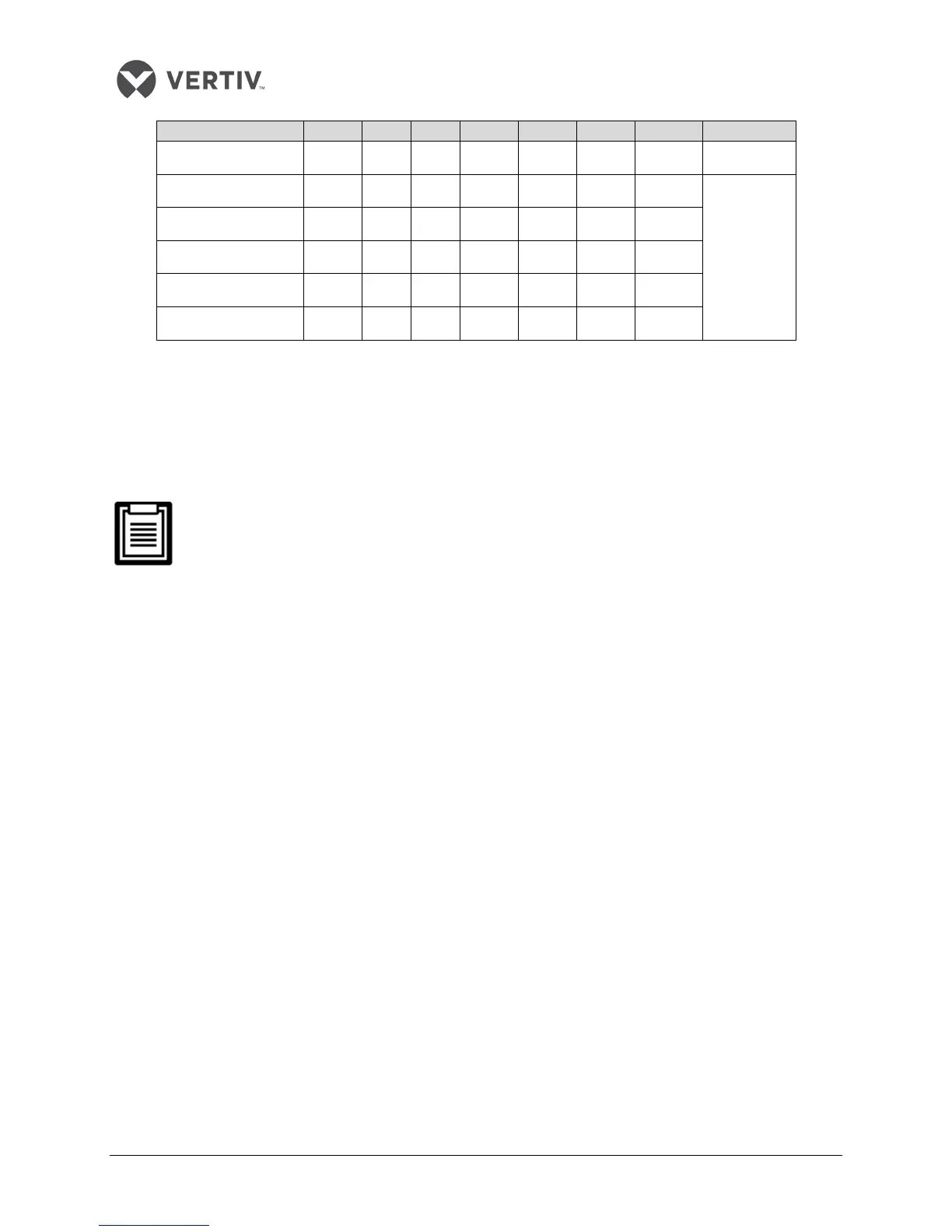
Rack temperature 5 0 0 0 1 0 1 11
Rack temperature 6 0 0 0 1 1 0 12
ON — “1”;
OFF — “0”
Rack temperature 7 0 0 0 1 1 1 13
Rack temperature 8 0 0 1 0 0 0 20
Rack temperature 9 0 0 1 0 0 1 21
Rack temperature 10 0 0 1 0 1 0 22
Remote Shutdown
As depicted in Figure 2-30, terminals 37# and 38# can be connected to the remote shutdown switch.
The terminals must be shorted before delivery. If a remote shutdown signal is to be connected, remove
the short-connect cable.
Closing the terminals 37# and 38# will shut down the unit.
Control signals of the outdoor unit
Terminals 70# & 71# are the control signal input terminals of the outdoor unit. Their On and Off state is
the same as that of the compressor 2#. They can be connected to the compression rotation speed-
control terminals on the control board of the outdoor unit. However, connecting them is an option
depending on the requirement.
External Common Alarm
Terminals 75# and 76# can be connected to the external common alarms. They generate signals to
external alarm devices such as an alarm indicator. When the critical alarm occurs, the contact will be
closed to trigger remote alarms, send signals to the building management system, or dial the paging
system automatically.
The users have to obtain the power supply of external common alarm system. For an in-depth definition
of the other terminals, refer to the Circuit Diagram
in
the Appendix-1.
Connecting the Solenoid valve of the Pipe Extension kit - (Optional for Site Installation)
The solenoid valve of the pipe extension kit consists of 2 control cables which are connected to their
respective terminals of the control board. For more specific connecting points on the interface board,
refer to the connecting terminal number of the liquid route solenoid valve depicted in the Circuit
Diagram in the Appendix-1 section.