Vertiv | Liebert CRV+ | User Manual 41
Rack sensor
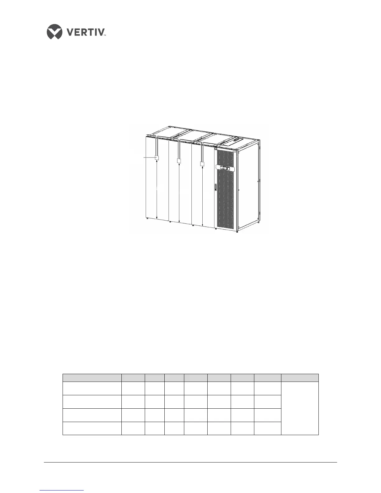
Each unit can be connected with a maximum of 10 temperature sensors. It is recommended that the
sensors be located in front of the heat loads to achieve the most precise temperature. If the sensors are
connected in series (see Figure 2-31), each temperature sensor monitors the temperature of air entering
each rack, and the read temperature value is used to control unit operation. The standard location of the
sensor is 1.5m height. Therefore, the sensors should be placed in positions as depicted in Figure 2-31, or
the devices cannot operate appropriately.
Figure 2-31 Layout figure of rack sensors
Following is the procedure to connect sensors for Liebert CRV+ models:
Insert the connector of the rack temperature sensor in the TB3 point. On connecting the cable,
route the cable through the top or bottom of the unit following which it should be connected to
the first sensor. Connect the first sensor to the second sensor. Thus, the sensors are connected in
a chain.
Fix the temperature in front of the hottest source inside the rack. Do not fix it in front of the
empty sub-rack. Affix the sensor on the rack surface using the magnets provided in the kit. Th
e
s
ensor must be fixed in a position that is mostly short of cool air.
Rack temperature sensor IRM-S0
1 address settings are depicted in the table in Listing 2.13.
Listing 2.13
Rack temperature 1 0 0 0 0 0 1 1
ON — “1”;
OFF — “0”
Rack temperature 2 0 0 0 0 1 0 2
Rack temperature 3 0 0 0 0 1 1 3
Rack temperature 4 0 0 0 1 0 0 10