Vertiv | Liebert CRV+ | User Manual 40
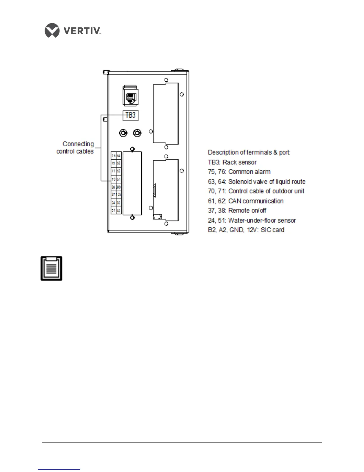
The location of the terminal block for cable connections in the site is depicted in Figure 2-28. The
amplified view of the terminals is shown in Figure 2-30.
Figure 2-30 Terminal Block for cable connection in the site
The connection personnel must take anti-static measures before connecting the control
cables
Water-under-floor sensor
If a water-under-floor sensor is equipped, connect one end of the sensor to terminal 51# and the other
end to common terminal 24#.
Each unit can be connected with multiple sensors in parallel, but there would be only one water-under-
floor alarm.
SIC card
If a SIC card is equipped, connect A#, B#, GND#, and 12# on the SIC card to the respective counterparts
on the terminal block. Refer to Appendix 1 Circuit Diagram fo
r in-depth information.