Vertiv | Liebert® CRV4 | User Manual 44
Electrical Installation
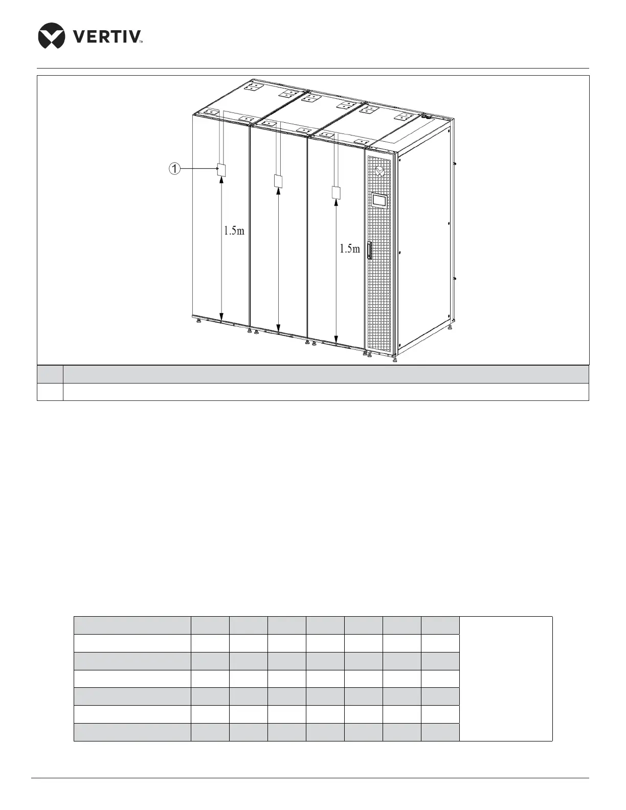
No. Description
1 Temperature sensor
Figure 4-4 Layout of Rack Temperature Sensors
Following is the procedure to connect sensors for Liebert® CRV4 models:
1. Insert the connector of the rack temperature sensor in the TB3 point. On connecting the cable, route the
cable through the top or bottom of the unit following which it should be connected to the rst sensor.
Connect the rst sensor to the second sensor. Thus, the sensors are connected in a daisy-chain.
2. Fix the temperature sensor in front of the hottest source inside the rack. Do not x it in front of the empty
sub-rack. Aix the sensor on the rack surface using the magnets provided in the kit. The sensor must be
xed in a position that is mostly short of cool air.
Rack temperature sensor IRM-S02TH address settings are given in the Table 4-3.
Table 4-3 IRM-S02TH Address Setting
Sensor 1 2 3 4 5 6 ID
ON — “1”;
OFF — “0”
Rack temperature 1 0 0 0 1 0 0 10
Rack temperature 2 0 0 0 1 0 1 11
Rack temperature 3 0 0 0 1 1 0 12
Rack temperature 4 0 0 0 1 1 1 13
Rack temperature 5 0 0 1 0 0 0 20
Rack temperature 6 0 0 1 0 0 1 21
 Loading...


