Vertiv™ | Liebert® EXM
™
50-250kVA, 480V, 60Hz User Manual | 27
The recommended wire for the connection from the EXM UPS to TB2 is as follows:
• MTW/TEW UL1015/UL1230
• 16 AWG, 600V, 105C, White/Black Twisted
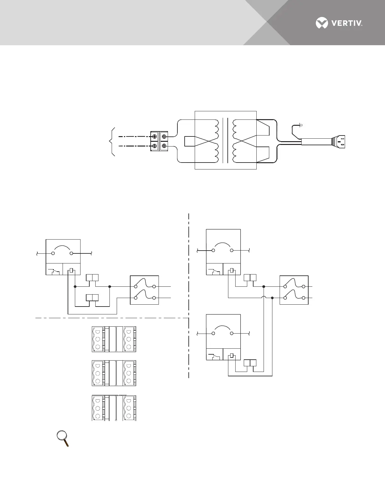
Figure 12 Alber BDSUi power wiring
Standard wire routing is handled internally between the Liebert
®
EXM
™
UPS and the matching
battery cabinet when both are bolted together. For external wiring between the Liebert
®
EXM
™
and the battery cabinet, follow the NEC or local codes.
Figure 13 Dual input back-feed breaker wiring when maintenance bypass cabinet not used
NOTE
Shunt trips are required in upstream breakers to allow back-feed protection to function properly.
480VAC from Liebert
EXM UPS output
To Alber
BDSUi
White
Black
Brown
Blue
Yellow/Green
TB2
Transformer
H1
H3
H2
H4
X4
X2
X3
X1
To
F9-4
To
F9-3
1. Auxiliary contacts not needed for back-feed breaker operation.
2. A 480V shunt trip coil is required for proper operation.
Dual Input Control Wiring
Upstream Bypass
Input Breaker
Upstream System
Input Breaker
Single Input Control Wiring
Back-Feed Breaker
Fuse Block (F7/F8)
Back-Feed Breaker
Fuse Block (F7/F8)
Upstream Rectifier
Input Breaker
UAM04030
Rev. 3
MX
MX
AUX
AUX
1
C2
C2
C1
C1
1
3
3
PH A
PH B
13
PH B
PH A
MX
AUX
1
C2
C1
3
J24
J24
J23
J23
BFP_O
BFP_S
BFP_C
INV_O
INV_S
INV_C
MAIN_O
MAIN_S
MAIN_C
MFP_O
MFP_S
MFP_C
RESV_O
RESV_S
RESV_C
RESV_O
RESV_S
RESV_C
1
3
5
1
3
5
1
3
5
24
6
24
6
24
6
J23
J24
J25