Vertiv™ | Liebert® EXM
™
50-250kVA, 480V, 60Hz User Manual | 40
remote stop switch between these two terminals using shielded cable (see Figure 21 and
Table 8). If this function is not used, terminals J2:3 and 4 must be opened and J2:1 and 2 must be
closed.
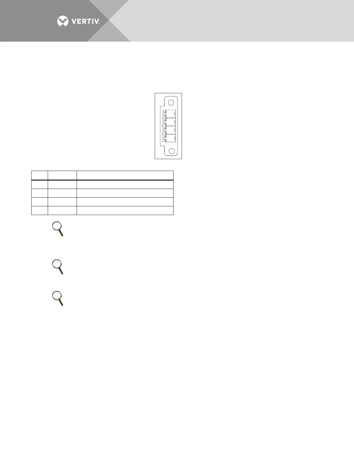
Figure 21 EPO wiring and signal names for J2
Table 8 EPO input contact relays—J2
Pin
Name Description
1 EPO-NC EPO activated when opened to Pin 2
2 + 12V EPO activated when opened to Pin 1
3 + 12V EPO activated when shorted to Pin 4
4 EPO-NO EPO activated when shorted to Pin 3
NOTE
The Emergency Stop action within the UPS shuts down the rectifier, inverter and static bypass. It
does not internally disconnect the input power supply. To disconnect ALL power to the UPS,
open the upstream feeder breaker(s) after the remote EPO is activated.
NOTE
Normally Closed EPO – J2: 1 and 2, these terminals are supplied factory-linked on the Bypass
Module on the UPS and must remain installed if using NO contacts.
NOTE
All auxiliary cables of terminal must be double-insulated. Wire should be 20-16AWG stranded for
maximum runs between 80 and 200 feet (25-60m), respectively.
EPO-NO
12V
J2
12V
EPO-NC
3214