Vertiv™ | Liebert® EXM
™
50-250kVA, 480V, 60Hz User Manual | 39
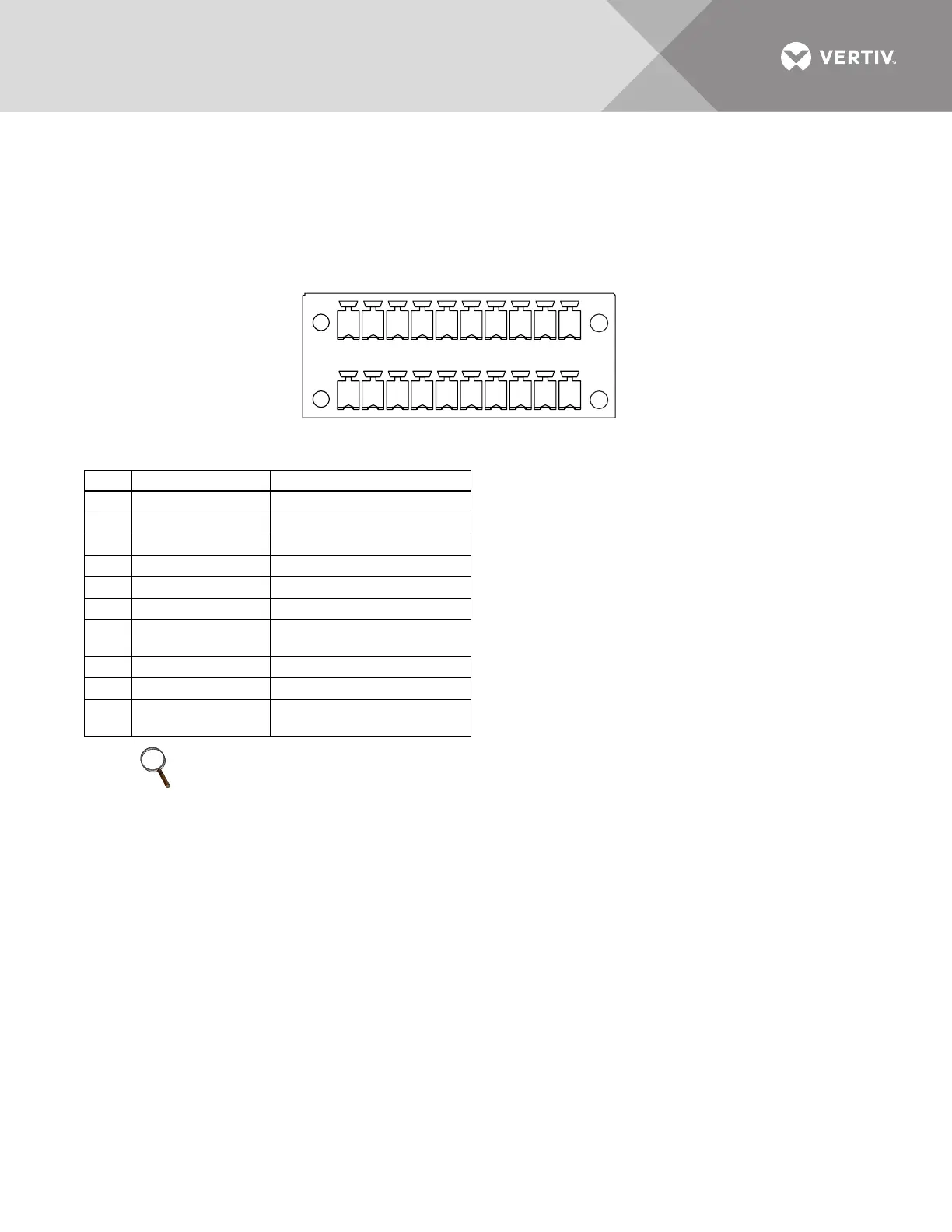
Figure 20 Battery cabinet interface—J22
3.4.5 EPO Input—Optional
NOTICE
Risk of exceeding internal voltage limits. Can cause equipment damage.
Do not apply more than 12V to the Emergency Power Off (EPO) input. Exceeding 12V on this input can
damage the Liebert
®
EXM’s
™
internal circuitry and control boards. Exceeding 12V will also put the
Liebert
®
EXM
™
in an EPO state, and the unit will not reset, making it non-functional.
The UPS has an Emergency Power Off (EPO) function operated by a button on the control panel
or by a remote contact provided by the user. The EPO button is under a hinged, clear plastic
shield.
The J2 connector, shown in Figure 21, is the remote EPO input interface. The EPO has NO/NC
contacts that become active when shorting terminals J2: 3 and 4 or open terminal connection
J2:2 and 1.
If an external Emergency Stop capability is required, it is connected at terminals J2: 1 and 2 and at
J2: 3 and 4 on the monitor board. It also is connected to the Normally Open or Normally Closed
Table 7 Battery cabinet interface—J22
Pin Name Description
1 12V_DRV BCB driver signal
3 BCB STATUS BCB state signal
5GND_DRY Dry ground
7 BCB_ON BCB on line signal
9NC NC
11 GND_DRY Dry ground
13 TMP_BATT
External Battery
temperature
15 12V_A Power
17 GND_DRY Dry ground
19
BATT_GND_FAUL
T
Battery ground fault signal
NOTE
All auxiliary cables of terminal must be double-insulated. Wire should be 20-16AWG stranded for
maximum runs between 80 and 200 feet (25-60m), respectively.
J22
111133155177199
2 4 6 8 10 12 14 16 18 20
12V_DRV
BCB_ON
GND_DRY
12V_A
GND_DRY
TMP_BATT
BCB STATUS
GND_DR
Y
BATT_GND_FAULT
NC