Vertiv™ | Liebert® EXM
™
50-250kVA, 480V, 60Hz User Manual | 33
Output System Connections—Ensure Correct Phase Rotation
7. Connect the system output cables between the UPS output busbars (OUT-A, OUT-B, OUT-C terminals)
and the critical load and tighten the connections to 428 lb-in. (48Nm) (M12 bolt).
Observe the battery cable polarity. Be sure that the battery connections, if any, are made with the correct
polarity.
8. Refit all protective covers removed for cable installation.
3.3 Control Cables Details
3.3.1 Static Bypass Assembly Features
Based on your site’s specific needs, the UPS may require auxiliary connections to manage the
battery system (external battery circuit breaker, battery temperature sensor), communicate with
a personal computer or provide alarm signaling to external devices or for Remote Emergency
Power Off (REPO). Terminations for these functions are located at the front of the static bypass
assembly. The main features are:
• Input and output dry contacts signal (one pair of contacts of relay)
• Emergency Power Off control (EPO)
• Environmental parameter input interface
• User communication (for data setting and user background monitor)
•Liebert
®
IntelliSlot
™
interface
• Temperature detect interface
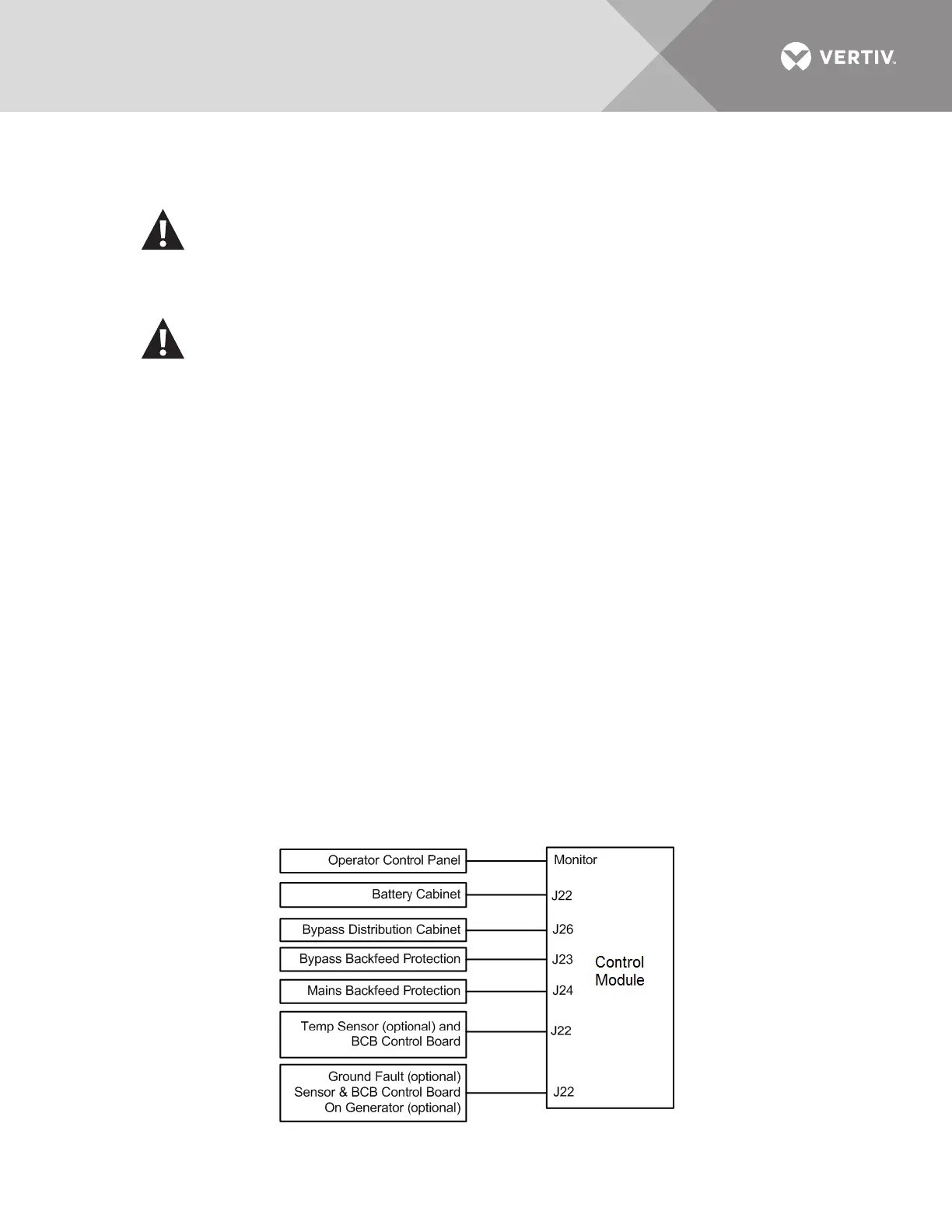
Figure 16 Control Module connections to display cabinet and options
WARNING
Risk of electrical shock and arc flash. Can cause property damage, injury and death.
If the load equipment will not be ready to accept power when the commissioning engineer
arrives, ensure that the system output cables are safely isolated.
AVERTISSEMENT
Risque de décharge électrique pouvant causer des blessures graves, voire mortelles.
Si les équipements branchés ne sont pas prêts à être alimentés à l’arrivée de l’ingénieur de
mise en service, assurez-vous que les bornes des câbles de sortie du système soient
isolées de façon sécuritaire.