Vertiv™ | Liebert® EXM
™
50-250kVA, 480V, 60Hz User Manual | 38
3.4.3 Liebert® MBC™ Interface
The Liebert
®
MBC
™
interface is on the Auxiliary Terminal Block at J26. Refer to Figure 18 for
circuit details.
3.4.4 Battery Cabinet Interface Connectors
The battery cabinet interface is on the Auxiliary Terminal Block at J22. Refer to Figure 20 for
circuit details.
J23
1BFP_O
Bypass back-feed normally open contact. Open when there is no
back-feed.
3 BFP_S Bypass back-feed common contact.
5BFP_C
Bypass back-feed normally closed contact. Closed when there is no
back-feed.
J24
2MAIN_O
Rectifier input state normally open contact. Open when the rectifier is
abnormal.
4 MAIN_S Rectifier input state common contact.
6MAIN_C
Rectifier input state normally closed contact. Closed when the
rectifier is normal.
NOTE
All auxiliary cables must be double-insulated and shielded. Wire should be 20-16AWG stranded
for maximum runs between 80 and 200 feet (25-60m), respectively.
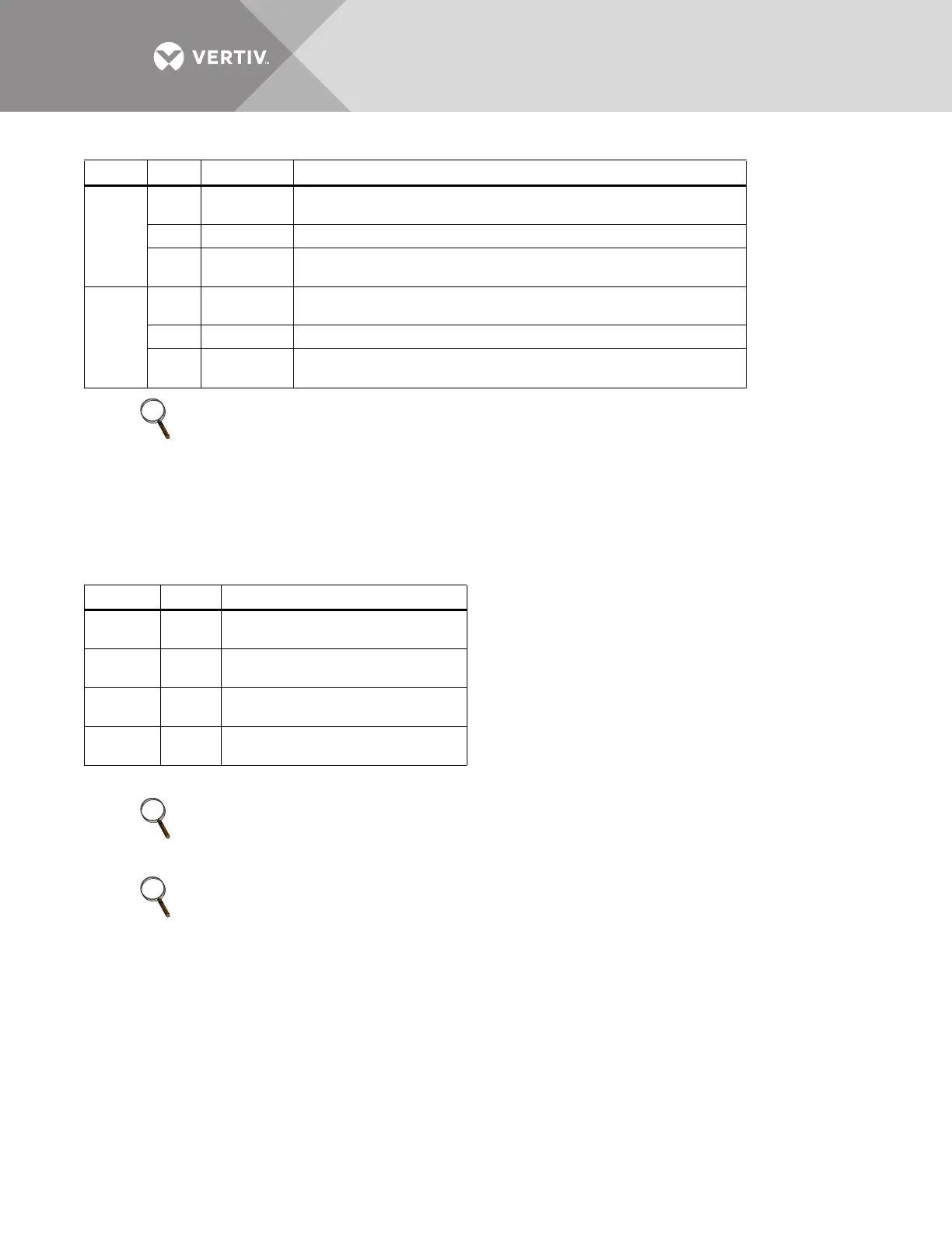
Table 6 Liebert® BDC interface
Position Name
Description
J26.1
Q1
STA
Main input switch status signal
J26.5
Q2
STA
Bypass input switch status signal
J26.9
Q3
STA
External maintenance switch status
signal
J26, 3, 7,
11
GND Ground for dry contacts
These contacts cannot be active unless they are set via software.
NOTE
All auxiliary cables must be double-insulated and shielded. Wire should be 20-16AWG stranded
for maximum runs between 80 and 200 feet (25-60m), respectively.
NOTE
Refer to SL-26103, the Liebert
®
EXM
™
Maintenance Bypass Cabinet manual for the Liebert® MBC
™
wiring.
Table 5 Output dry contact relays
Port Pin
Name Description