Vertiv | Liebert PEX4 | User Manual 28
Installation
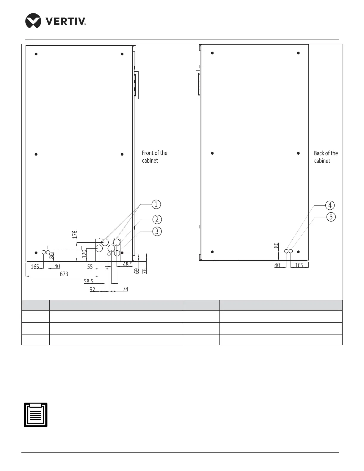
No. Description No. Description
1
Discharge pipe ø22
4 Condensate drain outlet
2
Liquid pipe inlet ø16
5 Humidication pipe inlet
3 Cable entry 65x25
Figure 2-15 Left and Right Panel with Nozzle Position of Cut-out Location Dimensions (unit: mm)
If it is diicult to connect the pipes from the base plate as per the cable layout, the knocking holes on the side
plate can also be used for the connection as shown in Figure 2-15. Select the inlet and outlet holes according to
the actual needs. Ensure only one service is used per opening.
The equipment has knock-outs, ensure to mount sleeve to the cable holes to avoid cutting the cables.
 Loading...


