VESDA
®
LaserCOMPACT Product Guide
19
The Air Inlet Port allows the pipe to be inserted up to 15 mm (0.60 in). To connect the detector to
the Pipe Network:
1. Ensure a minimum length of 500 mm (20 in) of straight pipe before terminating the pipe at
the air inlet port of the detector.
2. Square off and de-burr the end of the sampling air pipe, ensuring the pipe is free from swarf.
3. Insert the pipe into the inlet port ensuring a firm fit. DO NOT glue the inlet pipes to the Pipe
Inlet Manifold.
Air Exhaust Pipe
Unplug the air exhaust port at the bottom of the detector. If necessary pipe the exhaust back to
the relevant VESDA Zone. The maximum suggested length for the exhaust pipe is 4 m (13 ft.)
1.7 Wiring Connections
Termination Card
The Termination Card acts as the interface for VESDAnet (VN Model), VESDA Link (RO Model),
power supply Terminals, relay and relay Terminals.
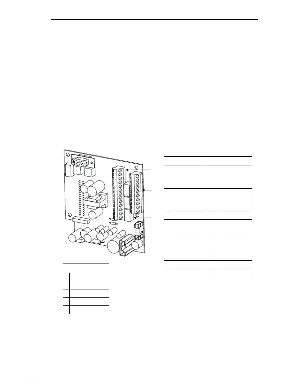
Figure 14 - LaserCOMPACT termination card VN Model (VLC-505)
NC = Normally Close
NO = Normally Open
C = Common
Terminal A Terminal B
1 Bias (-) (GND) 1 Shield
2 Reset (-)
(GPI)
2 VESDAnet A (-)
3 Reset (+)
(GPI)
3 VESDAnet A (+)
4 Bias (+) 4 Shield
5 LED (-) (GND) 5 VESDAnet B (-)
6 LED (+) 6 VESDAnet B (+)
7 FIRE (NO) 7 Power (-)
8 Fire (C) 8 Power (+)
9 Pre-Alarm (NO) 9 Power (-)
10 Pre-Alarm (C) 10 Power (+)
11 Fault (NO)
12 Fault (C)
13 Fault (NC)
A
B
C
D
Legend
A Terminal A
B Terminal B
C Relays
D 1.6 Amp Fuse
E VESDAnet Socket