LaserCOMPACT Product Guide VESDA
®
24
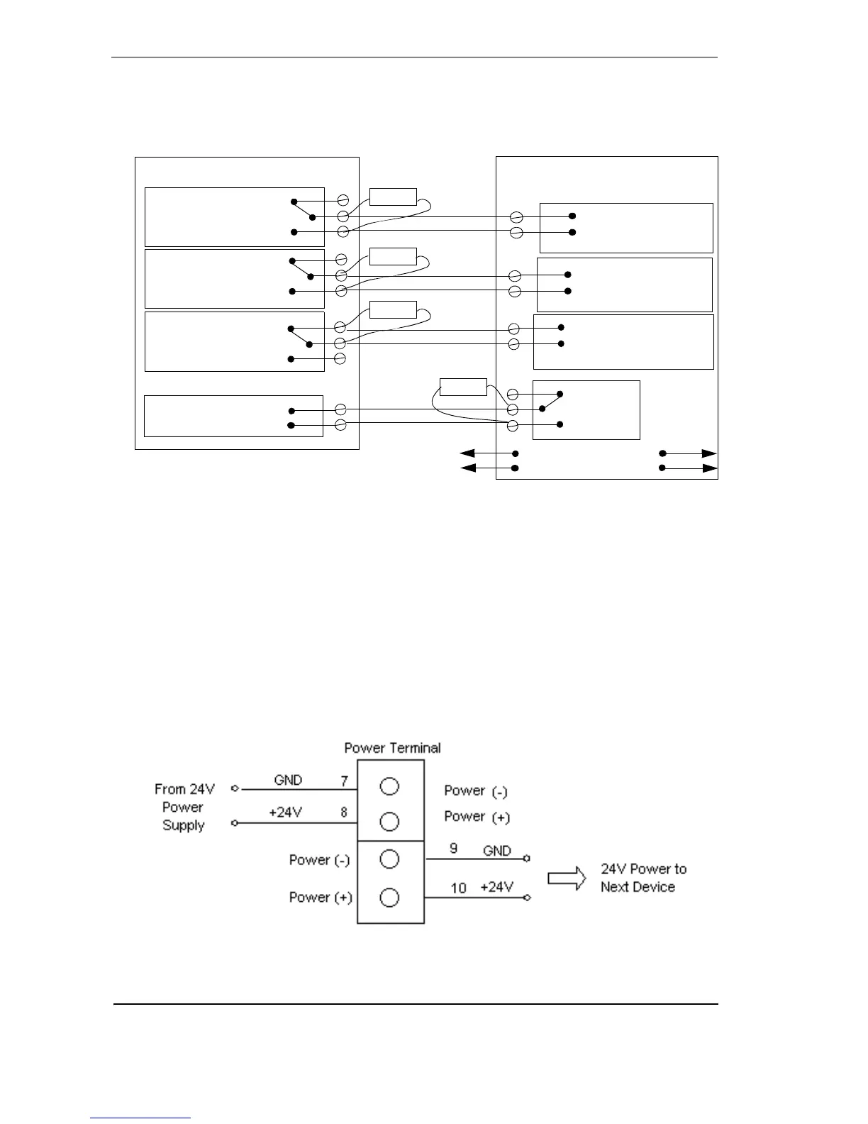
Wiring To an Address Loop Module.
This wiring example is for wiring VESDA detectors to a typical Address Loop module 3 input 1
output. These are example drawings. Refer to the appropriate product manual for the exact
wiring details of the third party equipment.
Figure 20 - Addressable Loop Module with EOL
1.8 Power source
The power terminals on the termination card connect to a 24 VDC power supply. The four power
terminals enable power to be brought into the detector via and looped out to another device. The
detector has reverse polarity protection to minimize the risk of reverse power connection to the
detector.
Note: The LaserCOMPACT detector will not operate when the power supply is reversed.
Note: Operating the detector outside the DC supply voltage range of 18 VDC and 30 VDC
may cause damage to the device.
Figure 21 - Wire connection details for power terminals on VN and RO model
termination card
Normally Closed (NC)
FIRE 1 Common (C)
Normally Open (NO)
Normally Closed (NC)
ACTION Common (C)
Normally Open (NO)
Normally Closed (NC)
FAULT Common (C)
Normally Open (NO)
GPI
(Set to reset)
(NC)
Reset (C)
(NO)
Fire Input
Short = Fire
Open = Wiring Fault
3 output 1 input Loop Module
Detector
EOL
Pre Alarm
Short = Fire
Open = Wiring Fault
Fault Input
Short= Detector Fault
Open = Wiring Fault
EOL
EOL
EOL
To Next Detector
To FACP