© 2010 Viking Preferred Service
32
Service Diagnostics and Procedures
Control Board Diagnosis
Bake Relay
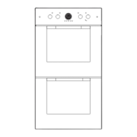
The DSOE and DDOE series oven use one
concealed bake element in the cavity floor. It is
connected on the control board to the Outer Bake
connection (Inner Bake is not used).
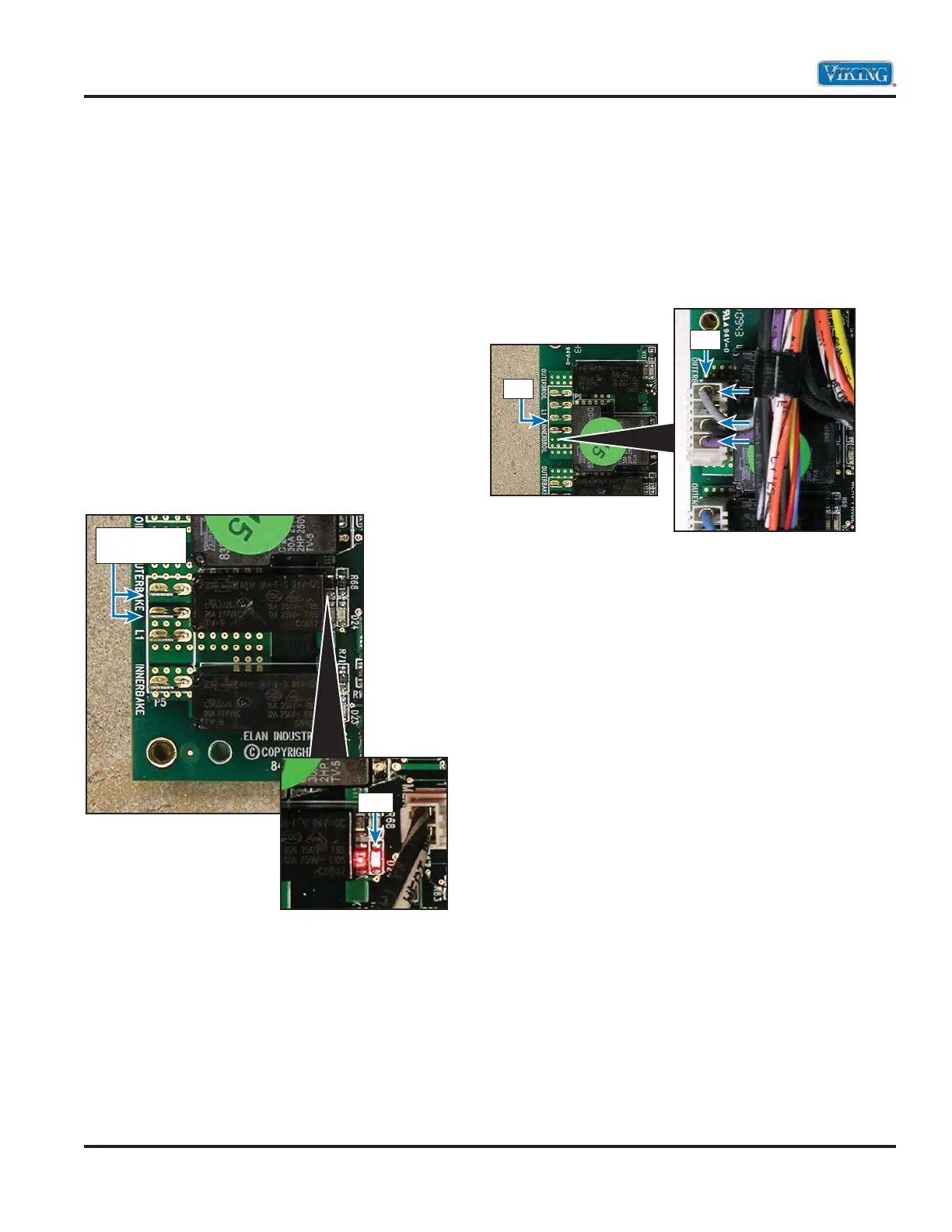
When the BAKE relay contact is energized
(red LED D24 at base of relay is illuminated red),
check for 240 VAC between the yellow wire at
the line break relay and the blue wire on P5.
If 0 VAC is measured, disconnect power and
remove P5 Molex plug. Reconnect power and
using an Ohm meter, check for continuity between
the relay contacts. When the relay is energized;
if infinite ohms (Ω) are measured, this indicates a
bad relay and replacement of the control board is
necessary. If 0 ohms are measured, the relay
contact is closing.
Broil Element
Locate the P6 connector and the line break relay
on the control board. The P6 connector will have a
Molex plug containing a violet, black, and gray wire.
The violet wire goes to the inner broil element, the
black wire is L1 input from main power supply, and
the gray wire goes to the outer broil element.
With the power off and Molex connector removed
from the P6 control board connection, use an
Ohm meter to measure resistance between the
violet wire in the Molex plug and the yellow
wire at the line break relay. This will measure the
resistance of the inner broil element and should
be approximately 24 Ω. Likewise, the outer broil
element can be measured by reading resistance
between the gray wire in the Molex plug and the
yellow wire at the line break relay. A resistance
of approximately 45 Ω should be found. If either
element fails to read resistance, remove the
element to repair or replace as necessary (see
Broil Element Disassembly, page 51).
Place meter
leads here
P-6
P-6
LED