Service Diagnostics and Procedures
© 2010 Viking Preferred Service 39
Control Board Diagnosis
RTD Sensor
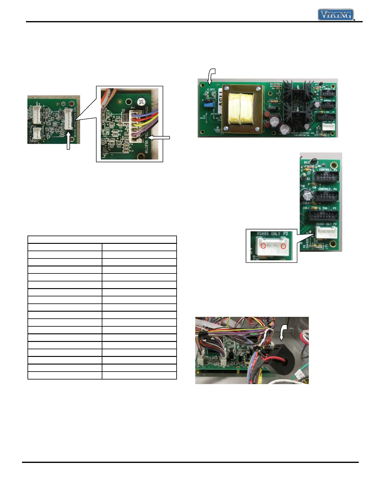
Locate the P14 connector on control board. The
P14 connector will have a Molex plug containing a
gray and violet wire. The gray and violet wires go to
the oven sensor.
With the Molex plug removed, use an Ohm meter
to measure resistance between the gray and violet
wires in the Molex connector. At room temperature
the reading should be approximately 1050 – 1100
Ω.
If Zero resistance (shorted RTD) or infinite resistance
(open RTD) is read, verify sensor wiring is connected
completely through circuit. If wiring is OK, replace
the sensor.
RTD Characteristics
RTD (Resistance Temperature Detector)
Temperature (˚F) Resistance (Approximate)
50 1038
75 1090
100 1143
200 1350
300 1553
350 1654
400 1754
450 1852
500 1950
550 2047
600 2153
650 2238
700 2332
750 2425
800 2318
850 2609
900 2700
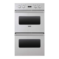
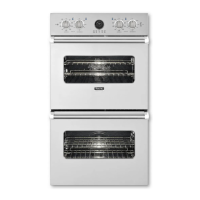
Note: Door switch must be depressed in order for
the Convection Fan and all convection cycles, Auto
Roast and Dehydrate heating elements to operate
when the door is opened.
Test Main Power Board
The main power board receives power directly
from the power supply. Verify 120 VAC between
Neutral (white wire) and L1 (black wire). If no voltage is
present, verify supply and check breaker.
With voltage present to the power board, verify the out put
voltage. Locate pin connection P2.
Output voltage can be checked
between pin 1 – 4 (see below).
Voltage should be 8VDC. If 0 volts
is read, replace the board.
P5 is the interface connection to the
upper relay board P13. P4 is the
interface connection to the lower relay board
board P13 and P3 is the interface
connection to the TOD (clock) user
interface.
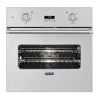
Amp Sensor
An current (Amp) sensor is used on the wall oven
to measure current flow. The DDOE301 and
DDOE305 have 2 on the unit. One for each cavity.
The amp sensor is placed around the L2 (red) feed
and connected to the control board.
To test the sensor, unplug the sensor and check
resistance across the two wires. A resistance
reading 28.2
Ω should be measured.
Note: The current sensor is only utilized in the
diagnostic mode. It is disabled
during normal operation.
P14
P14
120 VAC input
Linear Power Supply
1 2 3 4
Amp
sensor