© 2010 Viking Preferred Service
28
Service Diagnostics and Procedures
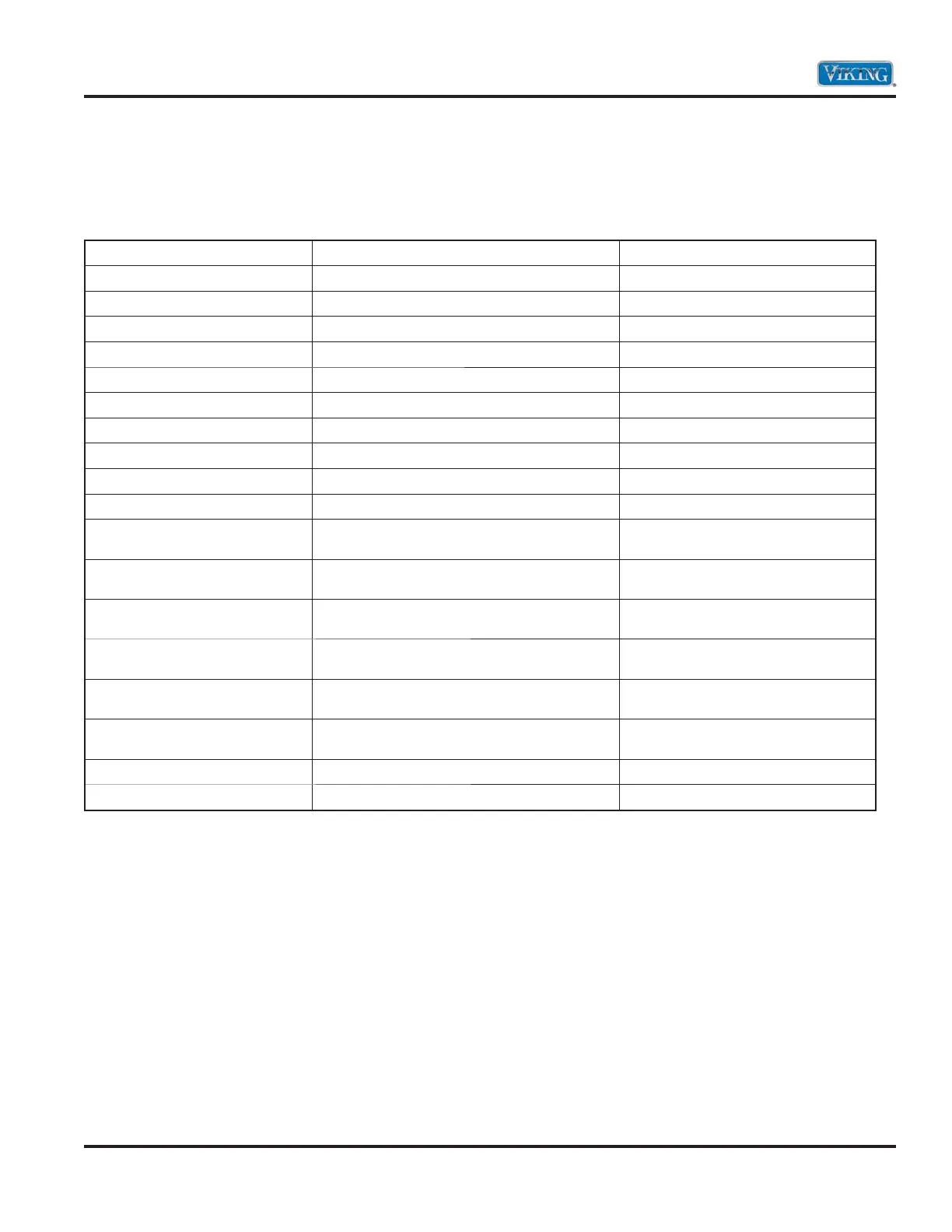
Control boards
The unit has an upper and lower control board that controls functions of the respective oven cavity.
Components can be diagnosed via the control board. With the control board accessed (see Control board
Access procedure, page 40), the following can be measured:
Component Oven Board Test Point Readings
Outer Bake Element (P5) Blue – line break Yellow
28.4 Ω
Inner Broil Element (P6) Violet – line break Yellow
23.7 Ω
Outer Broil Element (P6) Gray – line break Yellow
45.5 Ω
Convection Element (P2) White/Red – line break Yellow
34.4 Ω
Cooling Fan Motor (P11) White/Black – P(1) White (Power Board)
18.4 Ω
Convection Motor – Hi Speed (P4) Orange/Black – (P11) Dbl White
38.3 Ω
Convection Motor – Low Speed (P4) Orange/White – (P11) Dbl White
44.1 Ω
Oven Lights (P12) Yellow/Black – (P1) White (Power Board)
27.7 Ω
RTD (P14) Violet – (P14) Gray
1089 Ω @ room temp
Door Latch Motor (P12) Black/White – (P1) White (Power Board) 2180 k Ohms
Door Switch (P15) Gray – (P15) Brown (DL Com)
Infinite Ω door open
0 Ω door closed
Oven Light Switch (P15) Violet/White – (P15) Brown
Infinite Ω light switch off
0 Ω light switch on
Door Latch Switch (P15) Blue – (P15) Brown
0 Ω door unlocked Infinite Ω door
locked
Door Lock Switch (P15) Orange – (P15) Brown
Infinite Ω door unlocked
0 Ω door locked
Hall Effect Sensor (P8) Red – (P8) Black
425 Ω connector plugged in and
21.2M Ω connector unplugged
Hall Effect Sensor (P8) White – (P8) Black
9.9K Ω connector plugged in and
21.2M Ω connector unplugged
Clean Light (P1) Orange/Black – (P1) Violet
21.5M Ω
Cycle Light (P1) White/Black – (P1) Violet
21.5M Ω