© 2010 Viking Preferred Service
40
Service Diagnostics and Procedures
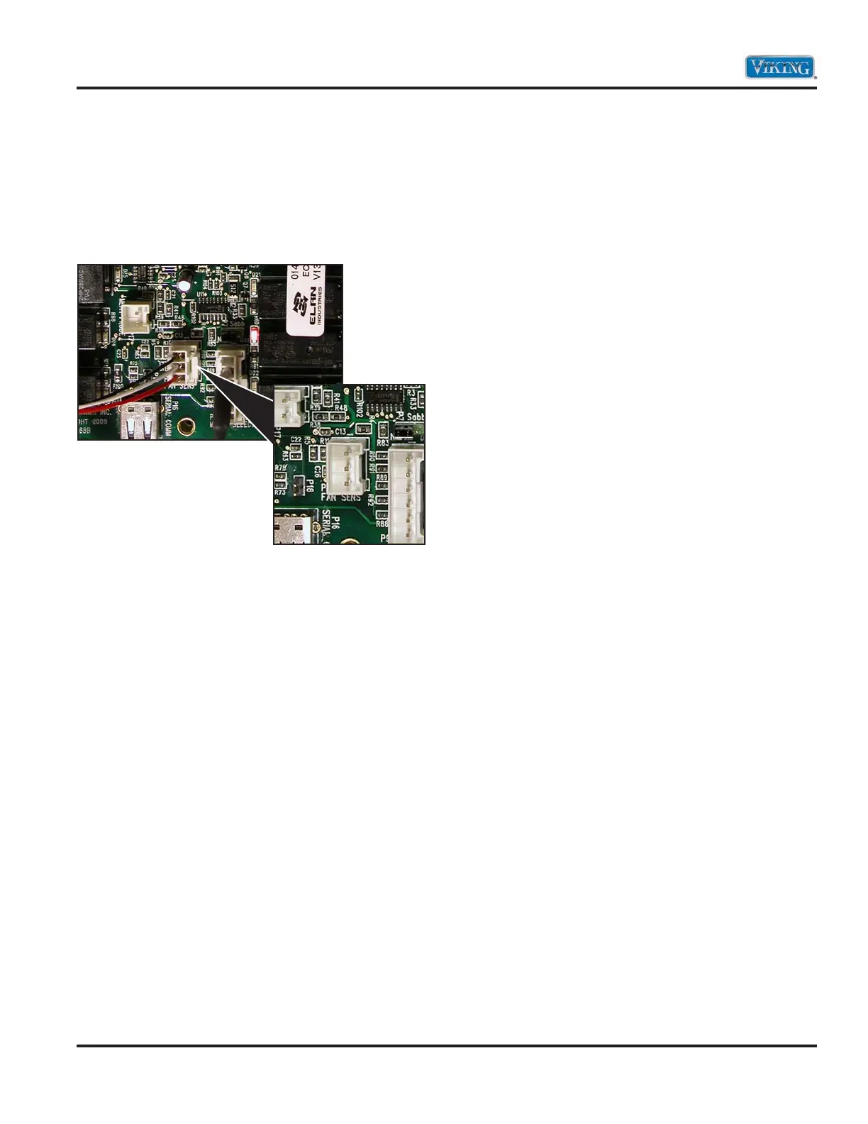
Hall Effect Sensor
The cooling motor incorporates a device called a
Hall Effect Sensor. The sensor is connected to the
control board. Below you will see the three wire
connectors to the Hall Effect Sensor, which consists
of a red (1), white (2), and black (3) wire. The Hall
Effect Sensor is built into the cooling motor.
To check the cooling fan, verify the cooling fan
is operating. If the fan is not turning, then verify
power is being supplied to the motor. If the fan
is running, locate the 3-wire Molex plug on the
control board. With the oven switched OFF, unplug
the connector from the board as shown above and
set the voltmeter to DC voltage.
A voltage of +5 volts between the pin (1) white
and pin (3) black should be measured. Measure the
voltage between pin (2) white and pin (3) black and
+5 volts should be measured as well. Measure the
voltage between pin (1) red and pin (2) white and
0 volts should be measured. If the voltages are not
correct and there is 120 volts supplied, replacement
of the control board is necessary. If the voltages
are correct, reconnect the 3-wire Molex plug. Place
meter leads in pin (1) red and pin (2) white.
Activate the oven so that the fan is energized.
With the fan turning, 2.5 VDC should be measured.
If 2.5 VDC is present, then connect meter leads
between pin (2) white and pin (3) black. A voltage
of 2.5 VDC should be measured. If 2.5 VDC is not
measured, but a full 5 VDC is measured, then the
Hall Effect Sensor is defective and replacement of
the cooling fan is necessary.
Another test that can be made is with the oven
shut off and the Molex plug connected, place
meter leads between pin (1) red and pin (2) white.
With the voltmeter set to DC voltage, a reading
of 0 or 5 volts should be measured depending on
where the motor is positioned. If the motor is spun
manually the voltage should jump between 0 – 5
volts. The same is true if the meter leads are placed
between pin (2) white and pin (3) black. As the fan
is manually spun a voltage of 0 to 5 volts will be
measured. Therefore, in any position, one side will
read 0 volts while the other will read 5 volts. This
is a good test to see that the three wire cable and
Hall Effect Sensor has closed contacts.