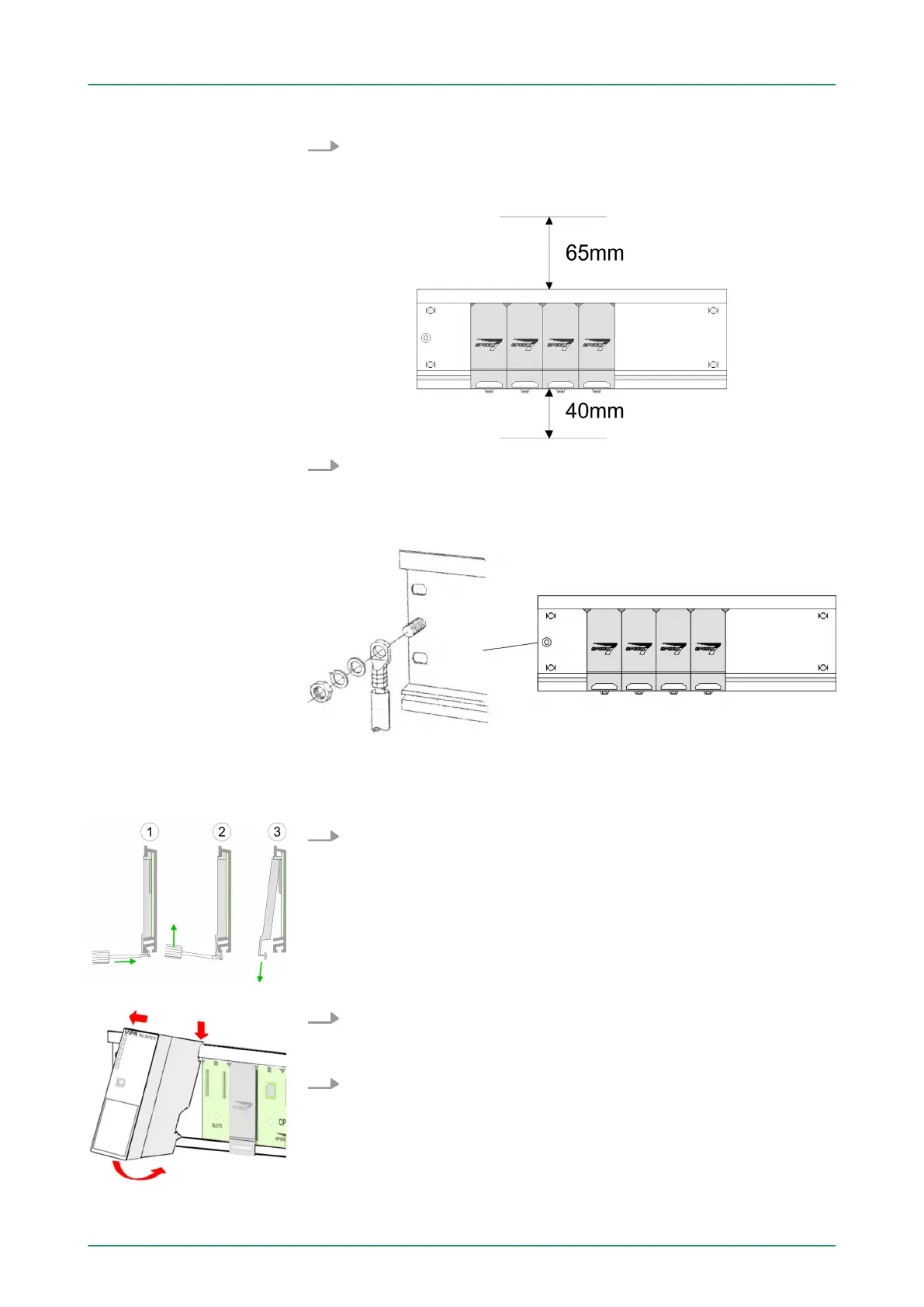
1. Bolt the profile rail with the background (screw size: M6), so that
you still have minimum 65mm space above and 40mm below
the profile rail. Please look for a low-impedance connection
between profile rail and background.
2. Connect the profile rail with the protected earth conductor
. The
minimum cross-section of the cable to the protected earth con-
ductor has to be 10mm
2
.
1. Dismantle the according protection flaps of the SPEED-Bus slot
with a screw driver (open and pull down).
For the SPEED-Bus is a parallel bus, not every SPEED-Bus slot
must be used in series. Leave the protection flap installed at an
unused SPEED-Bus slot.
2. At deployment of a DC 24V power supply
, install it at the shown
position at the profile rail at the left side of the SPEED-Bus and
push it to the left to the isolation bolt of the profile rail.
3. Fix the power supply by screwing.
Installation of the pro-
file rail
Installation SPEED-Bus
module
VIPA System 300S Assembly and installation guidelines
Assembly SPEED-Bus
HB140 | CPU | 314-6CF03 | GB | 16-43 21