Used area
Ä
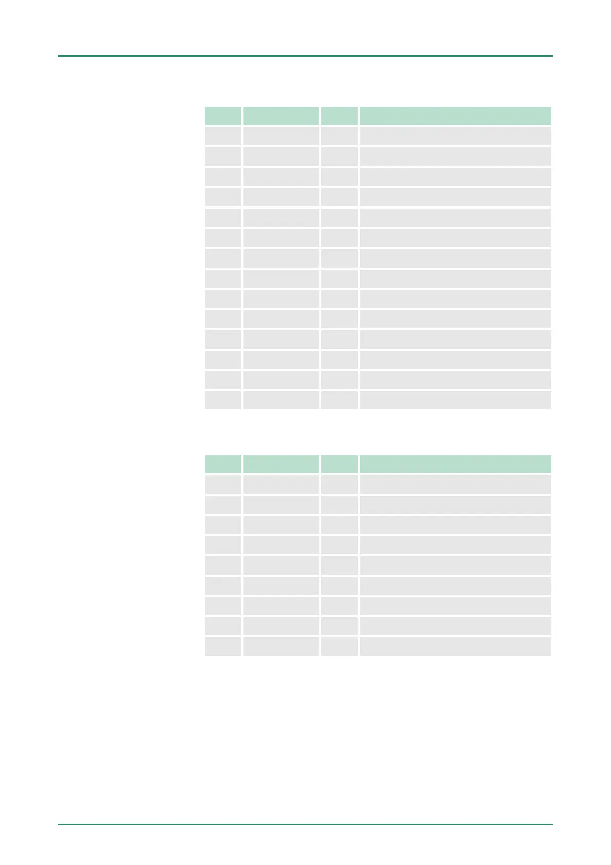
‘Input area’ on page 132
Addr. Name Byte Function
+0 DI_0 1 Digital input I+0.0 ... I+0.7
+1 DI_1 1 Digital input I+1.0 ... I+1.7
+16 CVCL_0 4 Counter value / latch value counter 0
+20 - 2 reserved
+22 ISTS_0 2 Input status counter 0
+24 CVCL_1 4 Counter value / latch value counter 1
+28 - 2 reserved
+30 ISTS_1 2 Input status counter 1
+32 CVCL_2 4 Counter value / latch value counter 2
+36 - 2 reserved
+38 ISTS_2 2 Input status counter 2
+40 CVCL_3 4 Counter value / latch value counter 3
+44 - 2 reserved
+46 ISTS_3 2 Input status counter 3
Used area
Ä
‘Output area’ on page 133
Addr. Name Byte Function
+0 - 1 reserved
+1 DO_1 1 Digital output Q+1.0 ... Q+1.7
+10 OSTS_0 2 Output status counter 0
+12 - 2 reserved
+14 OSTS_1 2 Output status counter 1
+16 - 2 reserved
+18 OSTS_2 2 Output status counter 2
+20 - 2 reserved
+22 OSTS_3 2 Output status counter 3
6.8 Counter - Fast introduction
n The CPU 314-6CF03 has 4 parametrizable counters integrated
that may be controlled separately.
n Each counter is controlled via an internal gate.
n The counter behavior and the assignment of the inputs is configu-
rable for each counter.
Overview
VIPA System 300S Deployment I/O periphery
Counter - Fast introduction
HB140 | CPU | 314-6CF03 | GB | 16-43 147