4. T
o view the process image select ‘View
è Display process image window’ or click at
.
ð
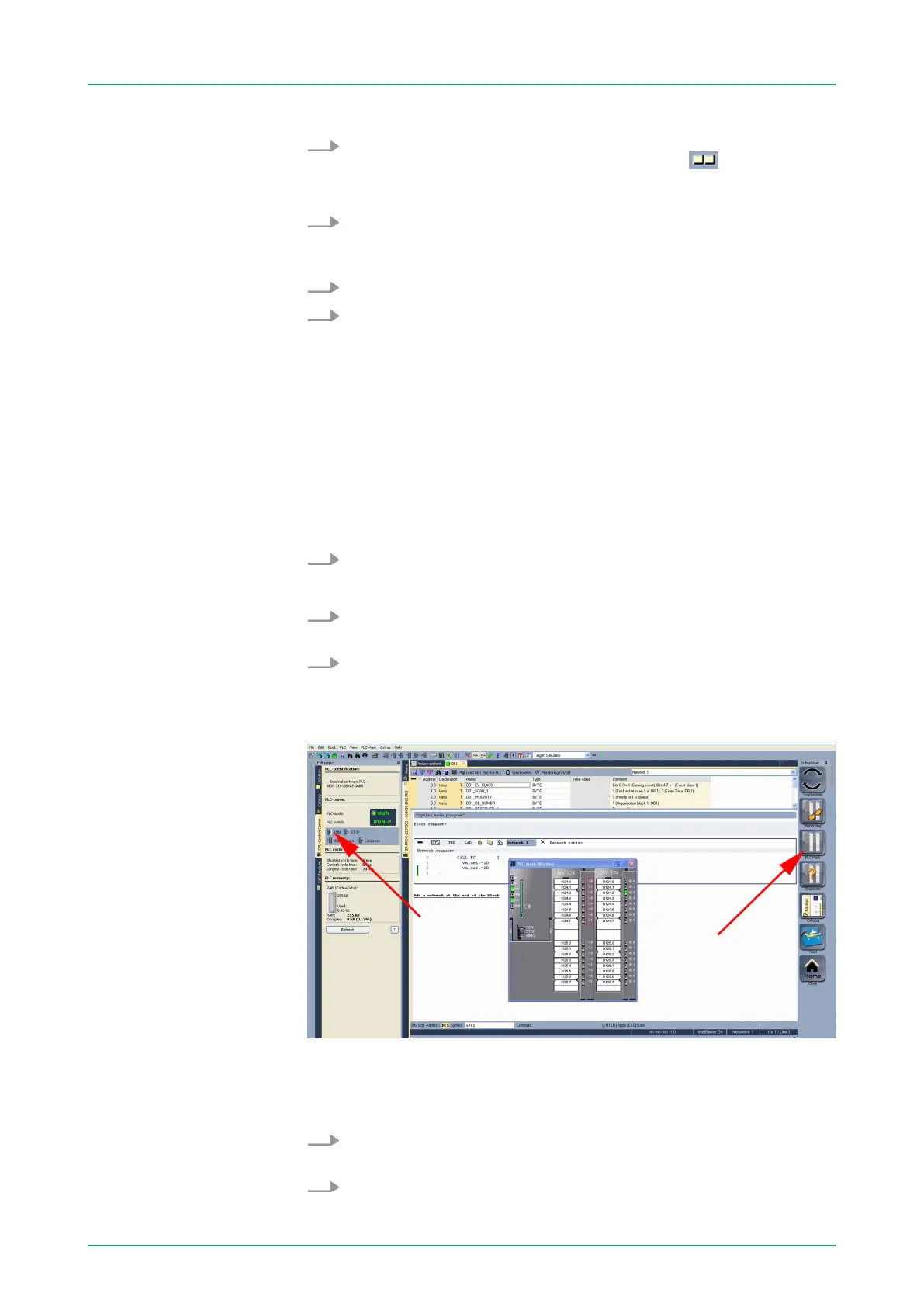
The various areas are displayed.
5. Double click to the process image and enter at ‘Line 2’
the
address PQB 124. Confirm your input with [OK]. A value marked
by red color corresponds to a logical "1".
6. Open the OB 1.
7. Change the value of one variable, save the OB 1 and transfer it
to the simulator
.
ð
According to your settings the process image changes
immediately. The status of your blocks may be displayed with
‘Block è Monitoring On/Off’.
A further component of the simulator is the PLC mask. Here a CPU is
graphically displayed, which may be expanded by digital and analog
peripheral modules. As soon as the CPU of the simulator is switched
to RUN state, inputs may be activated by mouse and outputs may be
displayed.
1.
Open the PLC mask
with ‘view è PLC mask’.
ð
A CPU is graphically displayed.
2. Double-click to the output module, open its properties dialog and
enter the Module address 124.
3. Switch the operating mode switch to RUN by means of the
mouse.
ð
Y
our program is executed and displayed in the simulator,
now.
9.3.4 Transfer PLC program to CPU and its execution
1. For transfer to the CPU set the transfer mode to "T
arget:
TCP/IP-Direct".
2. If there are more network adapters in your PC, the network
adapter may be selected via ‘Extras è Select network adapter
’.
Visualization via PLC
mask
Proceeding
VIPA System 300SWinPLC7
Example project engineering > Transfer PLC program to CPU and its execution
HB140 | CPU | 314-6CF03 | GB | 16-43 214