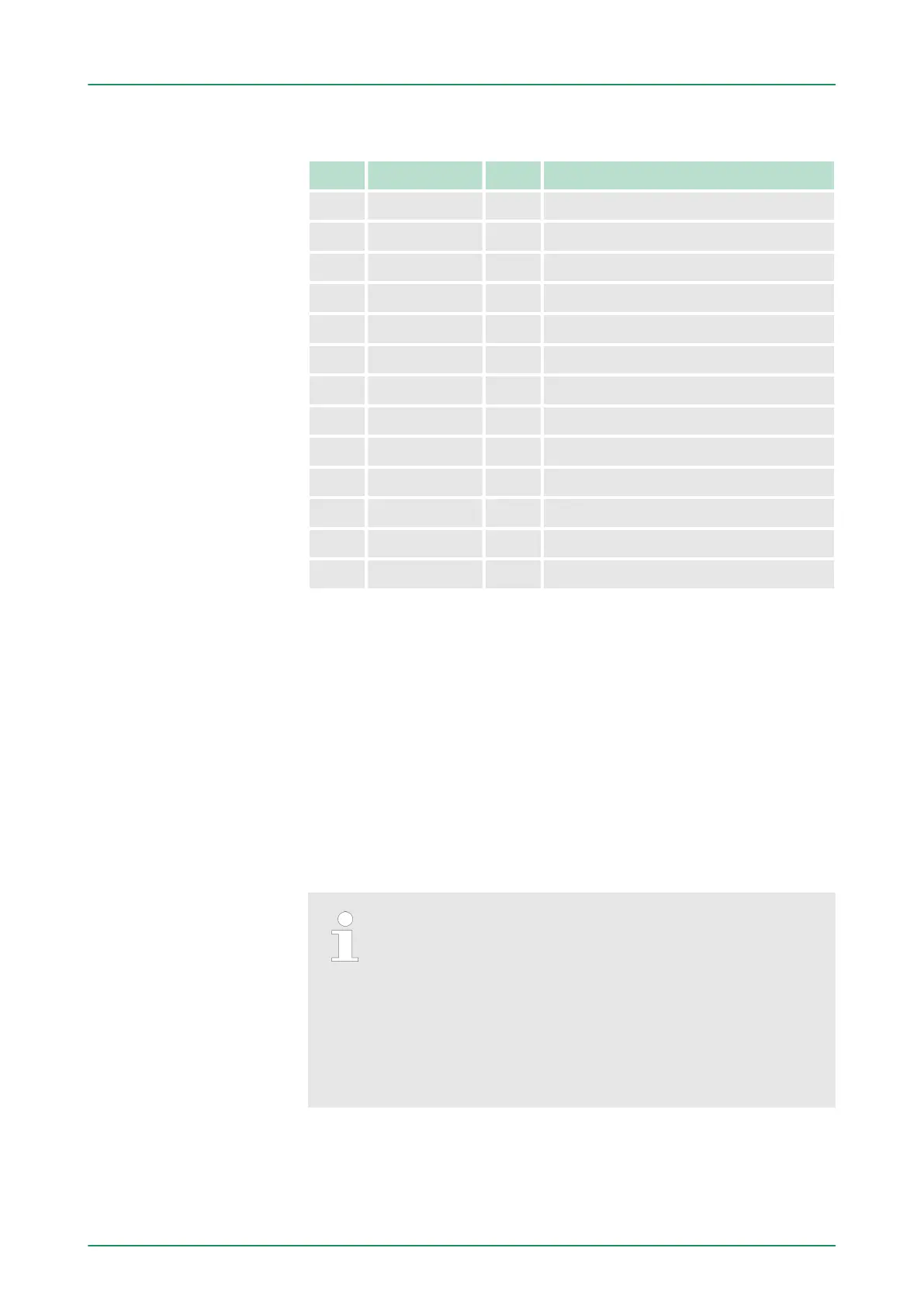
Output area
Addr. Name Byte Function
+0 - 1 reserved
+1 DO_1 1 Digital output Q+1.0 ... Q+1.7
+2 - 2 reserved
+4 AO_CH0 2 Analog output CH0
+6 AO_CH1 2 Analog output CH1
+8 - 2 reserved
+10 OSTS_0 2 Output status counter 0
+12 - 2 reserved
+14 OSTS_1 2 Output status counter 1
+16 - 2 reserved
+18 OSTS_2 2 Output status counter 2
+20 - 2 reserved
+22 OSTS_3 2 Output status counter 3
5.4 Hardware configuration - CPU
The configuration of the CPU takes place at the Siemens ‘hardware
configurator
’ . The hardware configurator is part of the Siemens
SIMATIC Manager. It serves for project engineering. The modules,
which may be configured here are listed in the hardware catalog. If
necessary you have to update the hardware catalog with ‘Options
è Update Catalog’.
For project engineering a thorough knowledge of the Siemens
SIMATIC Manager and the Siemens hardware configurator is
required.
Please consider that this SPEED7-CPU has 4 ACCUs.
After an arithmetic operation (+I, -I, *I, /I, +D, -D,
*D, /D, MOD, +R, -R, *R, /R) the content of ACCU 3
and ACCU 4 is loaded into ACCU 3 and 2. This may
cause conflicts in applications that presume an
unmodified ACCU 2.
For more information may be found in the manual
"VIP
A Operation list SPEED7" at "Differences between
SPEED7 and 300V programming".
Precondition
VIPA System 300S Deployment CPU 314-6CF03
Hardware configuration - CPU
HB140 | CPU | 314-6CF03 | GB | 16-43 59