A complete description of installation and deployment
of the terminating resistors is delivered with the con-
nector
.
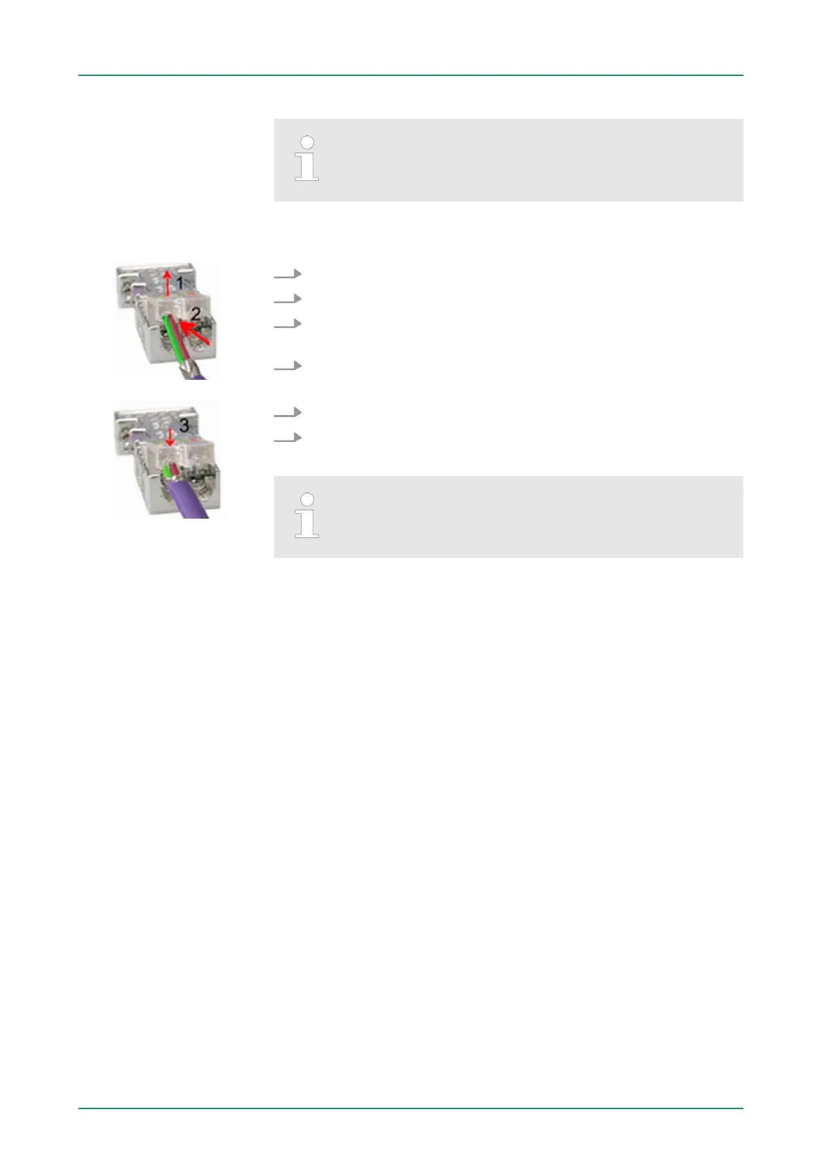
1. Loosen the screw
.
2. Lift contact-cover
.
3. Insert both wires into the ducts provided (watch for the correct
line colour as below!)
4. Please take care not to cause a short circuit between screen
and data lines!
5. Close the contact cover
.
6. T
ighten screw (max. tightening torque 0.08Nm).
The green line must be connected to A, the red line to
B!
8.7 Commissioning and Start-up behavior
In delivery the CPU is overall reset. The PROFIBUS part is deacti-
vated and its LEDs are of
f after Power ON.
The DP master can be served with bus parameters by means of a
hardware configuration. As soon as these are transferred the DP
master goes online with his bus parameter. This is shown by the RUN
LED. Now the DP master can be contacted via PROFIBUS by means
of his PROFIBUS address. In this state the CPU can be accessed via
PROFIBUS to get configuration and DP slave project.
If the master has received valid configuration data, he switches to
Data Exchange with the DP slaves. This is indicated by the DE-LED.
After PowerON respectively a receipt of a new hardware configuration
the configuration data and bus parameter were transferred to the DP
master. Dependent on the CPU state the following behavior is shown
by the DP master:
Assembly
Start-up on delivery
Online with bus param-
eter without slave
project
Slave configuration
CPU state controls DP
master
VIPA System 300S Deployment PROFIBUS communication
Commissioning and Start-up behavior
HB140 | CPU | 314-6CF03 | GB | 16-43 203