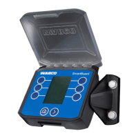
SmartBoard
Assembly and installation
40
5 Assembly and installation
Prior to installation, retrofitting, or repair of the SmartBoard, ensure the fol-
lowing instructions are observed:
Only trained and qualified personnel may perform this work.
Make sure to follow the specifications and instructions of the vehicle manufacturer.
Always comply with the company and national accident prevention guidelines and
Health and Safety regulations.
When working on the brake system, the vehicle must be secured against rolling
away.
Wear suitable protective clothing when necessary.
The workplace has to be dry, as well as sufficiently lit and ventilated.
– Make sure that you install the ADR version (446 192 111 0) of the SmartBoard
in ADR vehicles (see chapter 2.1 "SmartBoard for ADR (GGVS) vehicles",
page 9).
– Disconnect the power supply to the towing vehicle. Consider any risks with re-
gard to the short circuiting of batteries in the vehicle see chapter 1.1 "Measures
for avoiding electro-static charge and uncontrolled discharging (ESD)", page 7.
– Select the appropriate wiring diagram according to your system configuration
(see chapter 8.3 "Circuit diagrams", page 54).
– Select an installation location on the frame that is easily accessible for the user
and that can be reached by the planned connecting cable.
The installation location should be protected from spray water or be located on
the operating console.
– Use the drilling template for performing any drilling (see chapter 8.4 "Drilling
template", page 56).
– Fasten the device on vehicle frames with four M8 bolts and tighten the bolts se-
curely. Tightening torque: 15 Nm +/-15 %.
– Install cables according to the circuit diagram in parallel with already existing
wiring harnesses. Form large loops from ample lengths.
– Cable the SmartBoard with the Trailer EBS modulator. Press the cable plug-
connector into the slot applying a little initial force. All connections must be as-
signed a cable or have a closing cap.
– Fasten the cable only on solid elements that are connected with the compo-
nents, e. g. the vehicle frame. Fastening to flexible elements can cause cable
breaks and the seal can be broken.
Fasten the cable and plug so that no tension or lateral forces affect the plug-in
connections. Avoid laying cables across sharp edges or near aggressive media
(acids for example).
Fasten the cable a maximum of 30 cm after the device, e. g. with a cable tie.
The SmartBoard casing must not be opened unless the battery needs to be re-
placed by a specialist workshop.
It is not permitted to paint or spray the SmartBoard.
5.1 Cabling Instructions
SmartBoard connection to Trailer EBS D (circuit diagram 841 801 913 0)
The SmartBoard is connected to connection IN/OUT2 of the Trailer EBS D modula-
tor. CAN 2 must be activated with the diagnostic software.