SmartBoard
Assembly and installation
42
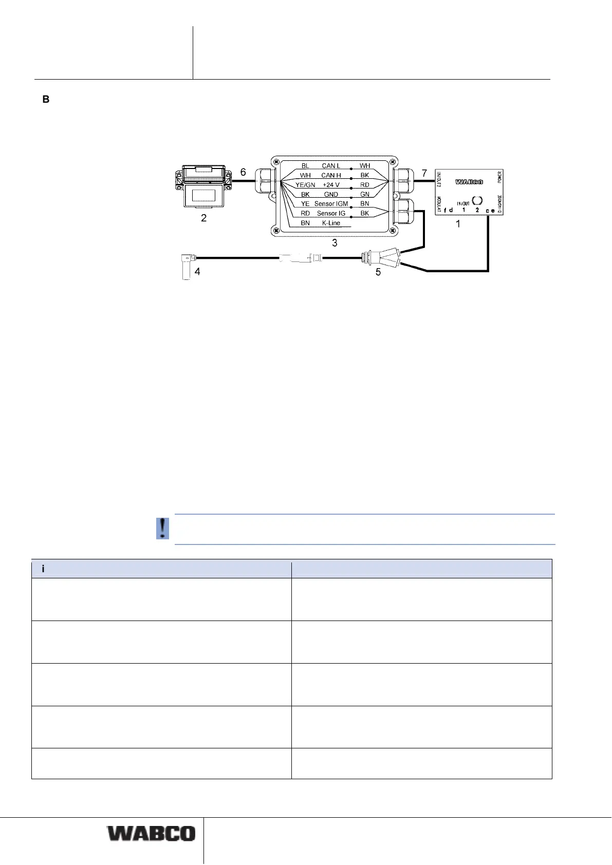
ABS sensor connection to the SmartBoard (only required with Trailer EBS D)
To operate the odometer counter of the SmartBoard in combination with Trailer
EBS D, an ABS sensor must be wired to the SmartBoard using a Y-cable. Connect
the cable ends in a junction box according to the diagram.
1 Trailer EBS D modulator 480 102 014 0
2 SmartBoard 446 192 110 0
3 Distribution box
4 ABS sensor 441 032 578 0 / 441 032 579 0
5 Y-cable 894 590 075 0
6 Cable 449 637 050 0
7 Line of cables 449 378 ... 0
5.2 Start-up
The SmartBoard is ready for operation immediately after it has been connected to
Trailer EBS. Parameter settings are only required in special cases.
– Connect the ABS connector to the towing vehicle and switch the ignition on.
– Implement special settings according to the table below if applicable.
If no Trailer EBS D ECU data are displayed (odometer, system information), check
activation of CAN 2 via diagnostics on Trailer EBS D.
Situation Sequence
The SmartBoard was previously operated with a differ-
ent Trailer EBS or the vehicle system configuration has
changed.
Execute the <AutoConfig> function from the <Tools>
menu (see chapter 4.4.14.4 "Auto Config", page 36).
Ensure the correct output of the internal odometer
(Trailer EBS E or Trailer EBS D and Y sensor cable)
Set the tyre parameters in the <Tyres> menu (see
page 33). This function is also available via the diag-
nostic software.
Setting the date and time so that messages can be
linked to the correct time of their occurrence (not avail-
able in ADR version 446 192 111 0)
Set the date and time in the <Clock> menu (see
page 32). This function is also available via the diag-
nostic software.
Set the language Set the language parameters in the <Language> menu
(see chapter 4.4.13 "Language", page 28). This func-
tion is also available via the diagnostic software.
Set further parameter values Parameter setting see chapter 6.4 "Diagnostic Soft-
ware „SmartBoard“", page 45.