Support Email/ Skype: service2@wansview.com 9
● Motion Detection alarm via E-Mail, FTP, SD card
● Free DDNS Service Embedded
● Compatible with free PC Central Management Software
● Compatible with free iOS and Android APP
● Supports WPS - One Button Push Secure Wireless Connection
● Supports IEEE 802.11n Wireless Connection
● Supports WEP, WPA and WPA2 Encryption
● Waterproof IP66 for outdoor use
● Support ONVIF and RTSP protocol
● Plug and Play is optional
2. Device Connection
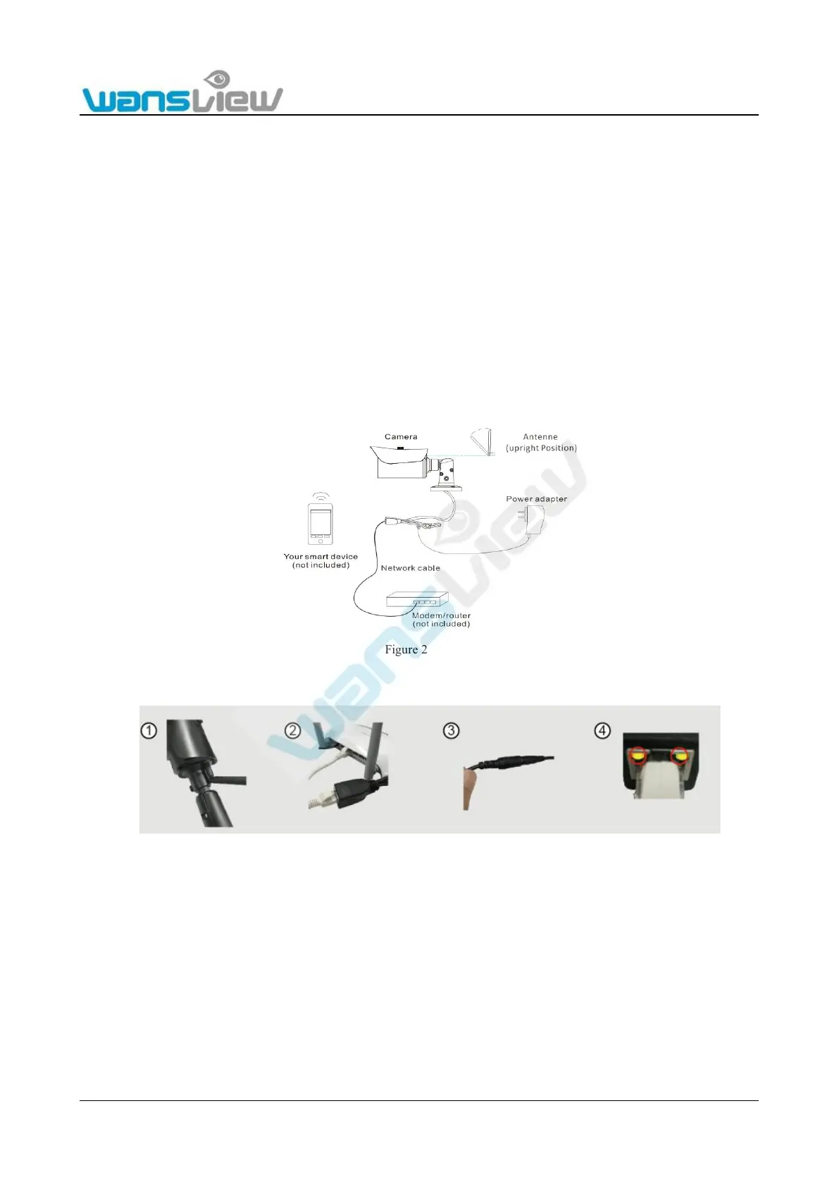
2.1 Connection Diagram
Figure 2.1.1
Steps for product connection:
Figure 2.1.2
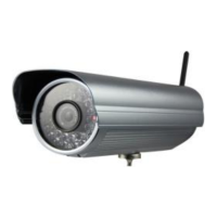
1. Please install and tightly screw in the accessory Wi-Fi antenna into the antenna aperture on the back of the camera.
2. Connect the IP camera and router via network cable.
3. Use the accessory power adapter to power up the camera (Please verify the output voltage of the adapter and the allowable
voltage value of the camera).
4. Observe the two lights at the network interface. When the orange light on the left side is ON, it indicates that someone is
accessing the camera. When the green light on the right side is ON, it indicates that the network is connected.
You can access the IP camera following the four steps above via a computer by using the power adapter to power up the camera and
connecting the IP camera and router via network cable, or via Wi-Fi. However, before the connection, camera Wi-Fi configuration is
required (under such circumstances, camera Wi-Fi should be configured for the Wi-Fi of the current router so that the camera can be
detected by the LAN computer). For detailed information, please refer to section 2.2 Wi-Fi Set Up.