2011980_d•en•2015-12-01 We reserve the right to make technical changes
7
The WAREMA climatronic WebControl is connected to the WAREMA cli-
matronic control panel via the controlbus. Power must be supplied to the
WAREMA climatronic WebControl from the WAREMA climatronic power
supply unit.
The WAREMA climatronic WebControl is also connected to your existing
configured router via the included LAN cable.
(One WAREMA climatronic WebControl can be connected per router.)
"DHCP" must be enabled on the router in order for the IP address to be as-
signed automatically. If this is not possible, please read the information pro-
vided under "DHCP" (Chapter 8 on page 27).
The second connection on your control panel is where the climabus and its
switch actuators and sensors are located.
The router uses the LAN to communicate with the PC or laptop and the
WLAN to communicate with mobile devices such as tablets or smartphones.
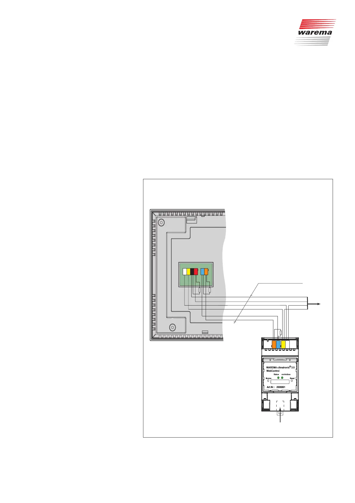
2.4 Wiring diagram
JY(St)Y 4x2x0.8 mm ∅
Bus A
Bus B
0 V
24 V DC
to other
bus devices
climabus
Bus A
Bus B
controlbus
terminating resistance120Ω
120Ω per terminating restistance
Ethernet
max. line length 200 m
X7
WH
YE
RD
BK
OG
BU
WH
YE
OG
BU
Fig. 3 Wiring diagram
Introduction