2011980_d•en•2015-12-01
We reserve the right to make technical changes
8
WAREMA climatronic® WebControl
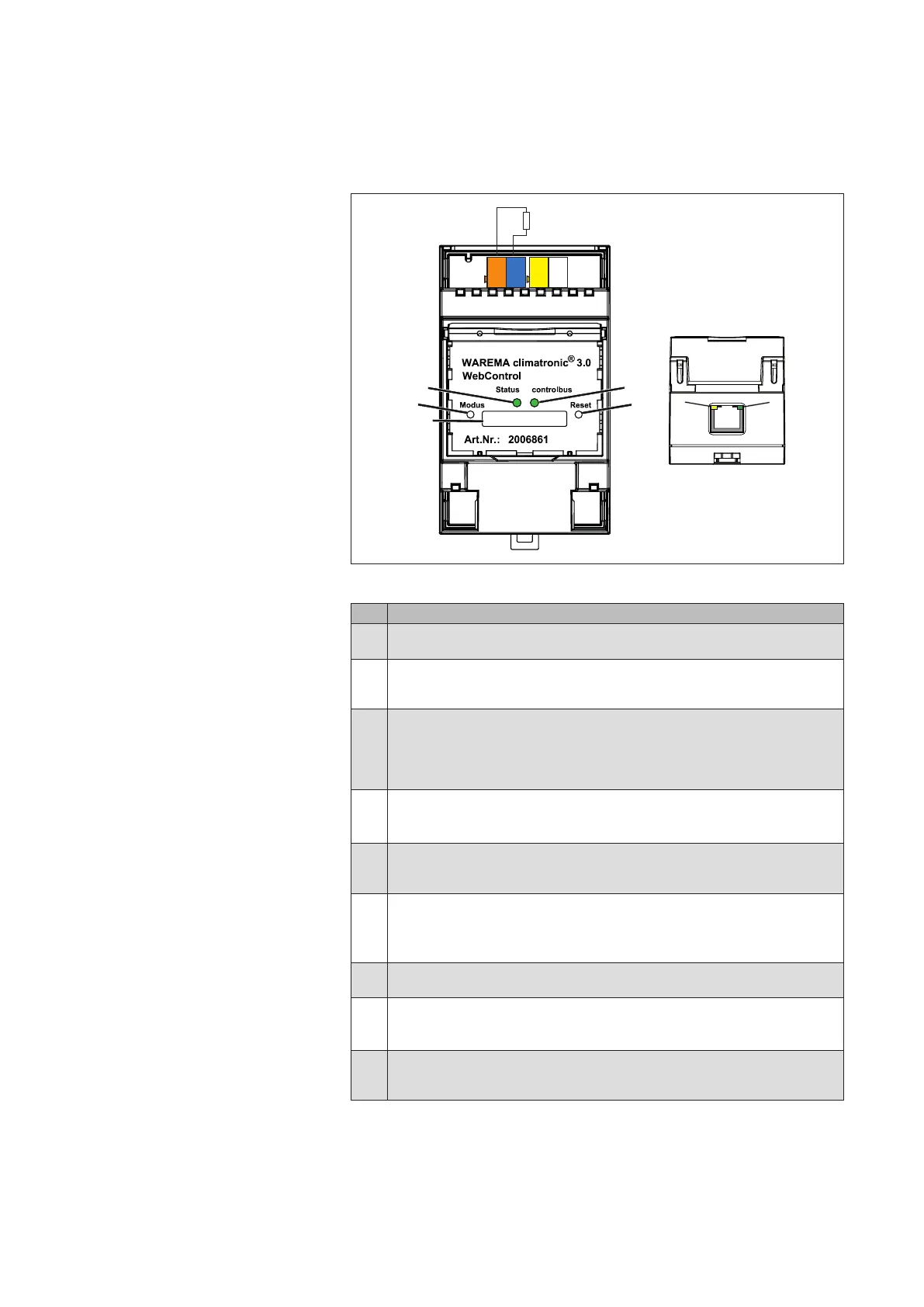
2.5 Connections and LEDs
terminating resistance120Ω
Fig. 4
Connections and LEDs on the WAREMA climatronic WebControl (front, bottom)
Pos. Function
Mode button
Resets device to the factory settings (see 7.2 on page 26)
Reset button
Short press (< 1 s): restarts device (power reset)
Long press (> 5 s): loads firmware (see Chapter 7.1.1 on page 25).
Status LED
Lights up briefly in orange after switching on, then red.
LED shines steady red: IP address not acquired, no router connection
LED shines steady green: IP address acquired, project available
LED flashes green: IP address acquired, no project loaded yet.
controlbus LED
Shines or flashes to indicate communication between the WAREMA clima-
tronic and the WAREMA climatronic WebControl.
SD card slot
Storage option for backup copies of the project and loading projects and
firmware/application updates (see Chapter 7.1.1 on page 25).
control bus connection
The WAREMA climatronic WebControl is connected to the WAREMA clima-
tronic via the orange/blue terminals.
A 120 terminating resistor is premounted between the terminals.
climabus connection
The power supply is connected using the yellow/white terminals.
RJ45 socket, yellow LED
Flashes when there is data traffic between the WAREMA
climatronic Web-
Control and the IP router.
RJ45 socket, green LED
Remains lit when the physical connection between the WAREMA climatronic
WebControl and the IP router is functional.
NOTE If an IP address is not assigned after 1min., the status LED flashes red. To
acquire an IP address in this case, see Chapter8 on page 27.
Introduction