8
Technical Specifications
8-6 | CFW-11 RB
8
(1) Steady-state rated current in the following conditions:
- Indicated switching frequencies or lower. For higher switching frequency consult WEG.
- Models on frame sizes E (only line 500...690 V), F and G are not allowed to operate at 10 kHz switching frequency.
- Surrounding air temperature as specified in tables. For higher temperatures, the input current must be derated according to Chapter 3 INSTALLATION
AND CONNECTION on page 3-1.
- Relative air humidity: 5 % to 95 % non-condensing.
- Altitude: 1000 m (3.300 ft). Above 1000 m (3.300 ft) up to 4000 m (13.200 ft) the output current must be derated by 1 % for each 100 m (330 ft) above
1000 m (3.300 ft). 2000 m to 4000 m above sea level – derating of 1.1% of the maximum voltage for each 100m above 2000 m.
- Ambient with pollution degree 2 (according to EN50178 and UL508C).
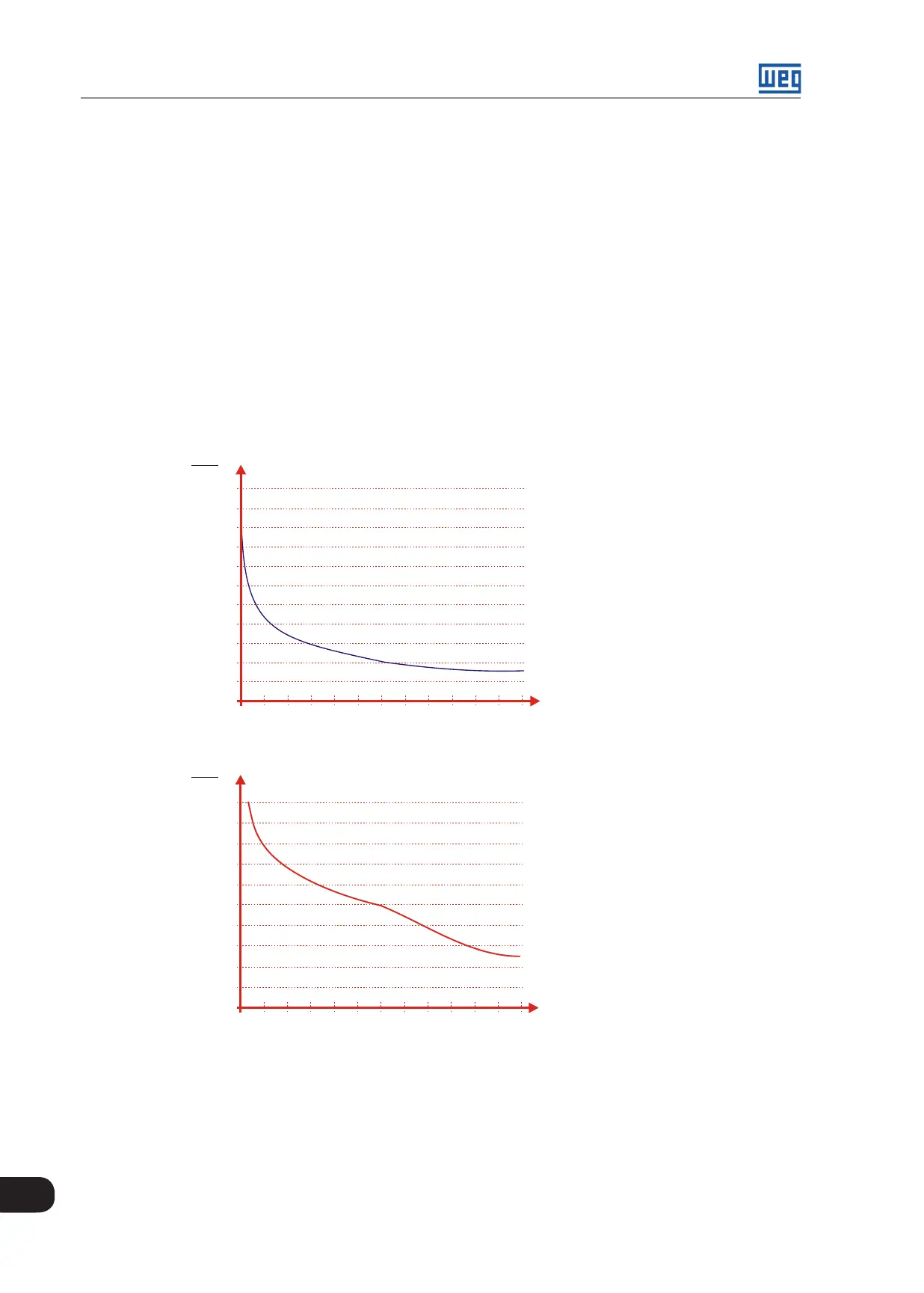
(2) One overload each 10 minutes. Table 8.1 on page 8-2 to Table 8.4 on page 8-5present only two points of the overload curve (activation time of 1 min
and 3 s). The complete IGBT overload curves for Normal Duty (ND) and Heavy Duty (HD) cycles are presented in Figure 8.1 on page 8-6.
Depending on the converter operational conditions such as surrounding air temperature and output frequency, the maximum time for operation of the
converter with overload may be reduced.
(3) The information provided about the converter losses is valid for the rated operating condition, i.e., for rated output current and rated switching frequency.
(4) ) In frame size E, F and G, for operation with voltage on the DC link above 650 Vdc for P0296 = 1, 2, 3 and 4 (380, 400 / 415, 440 / 460 and 480 V), above 810
Vdc for P0296 = 5, 6 and 7 (500 / 525, 550 / 575 and 600 V) and above 940 Vdc for P0297 = 8 (660 / 690 V), it is necessary to derate the input current. The
derating is proportional to the difference between the DC link voltage and the voltage limit (650, 810 or 940 V, depending on the value of P0296). The derating
is 10% for DC link voltage of 800 Vdc for P0296 = 1, 2, 3 and 4 (380, 400 / 415, 440 / 460 and 480 V), 1000 Vdc for P0296 = 5, 6 and 7 (500 / 525, 550 / 575
and 600 V) and 1200 Vdc for P0296 = 8 (660 / 690 V).
(5) The switching frequency may be automatically reduced to 2.5 kHz, depending on the operating conditions (ambient temperature around the inverter, output
current, etc.) - if P0350 = 0 or 1. If it is necessary to operate always at 5 kHz, set P0350 = 2 or 3; in this case it is necessary to derate the inverter rated input
current. In order to do so, contact WEG.
.
2.0
1.9
1.8
1.7
1.6
1.5
1.4
1.3
1.2
1.1
1.0
0.9
0 10 20 30 40 50 60 70 80 90 100 110 120
I
o
I
nom ND
∆ t (s)
(*) Attention!
One overload each
10 minutes.
(*)
(a) IGBTs overload curve for the Normal Duty (ND) cycle
2.0
1.9
1.8
1.7
1.6
1.5
1.4
1.3
1.2
1.1
1.0
0 10 20 30 40 50 60 70 80 90 100 110 120
I
o
I
nom HD
∆ t (s)
(*) Attention!
One overload each
10 minutes.
(*)
(b) IGBTs overload curve for the Heavy Duty (HD) cycle
Figure 8.1: (a) and (b) - Overload curves for the IGBTs