10
FAULTS AND ALARMS
Table 10.2: Option of parameter P352
P352 Action
0 = OFF Fan off
1 = ON Fan on
2 = CT Fan is controlled via software
10.3.2 Motor
The inverter has a function to protect the motor from overtemperature by indicating fault F078. The motor must
have a triple PTC type temperature sensor. The sensor can be read through the analog inputs.
For the reading of the PTC, it is necessary to configure it for current input and select the option “4 = PTC” in P231
or P236. Connect the PTC between the supply +10 Vdc and the analog input.
The analog input reads the PTC resistance and compares it to the limits for the fault. When those values are
exceeded, fault F078 is indicated. As shown in Table 10.3 on page 10-4.
!
WARNING!
The PTC must have reinforced insulation of the live parts of the motor and other installations.
Table 10.3: Actuation levels of fault F078
PTC Resistance AIx Overtemperature
R
PTC
< 50
Ω V
in
> 9,1 V F078
50 Ω < R
PTC
< 3,9 kΩ 9,1 V > V
in
> 1,3 V Standard
R
PTC
> 3,9 kΩ V
in
< 1,3 V F078
✓
NOTE!
For this function to work properly, it is important to keep the gain(s) and offset(s) of the analog inputs
at the factory setting values.
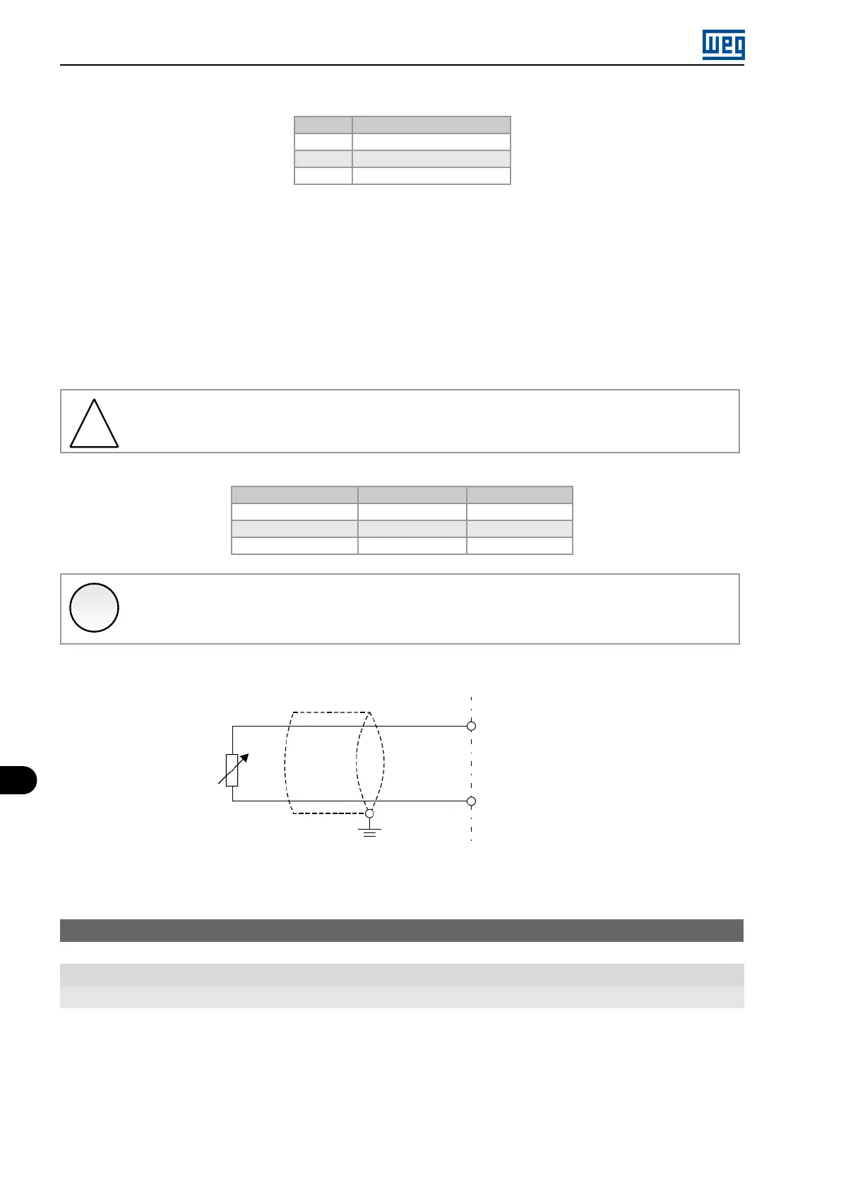
Figure 10.1 on page 10-4 shows the connection of the PTC to the inverter terminals via analog input.
AIx (0 .. 4 to 20 mA)
PTC
+ 10 V
Figure 10.1:
Connection of the PTC to the frequency inverter
P037 - Motor Overload Ixt
Range: 0.0 to 100.0 %
Properties: ro
Description:
It indicates the present motor overload percentage or overload intergrator level. When this parameter reaches 6.3
% the inverter will indicate the motor overload alarm (A046). Or when this parameter reaches 100,0 % the ”Motor
Overload” fault (F072) will occur (F072).
Figure 10.2 on page 10-5 shows the actuation time of the overload as a function of the output current (P003)
normalized in relation to the overload current (P156, P157 or P158).
10-4 | Micro Mini Drives