15
APPLICATION EXAMPLES
15.1.2 Application 2 - Simple application (overspeed)
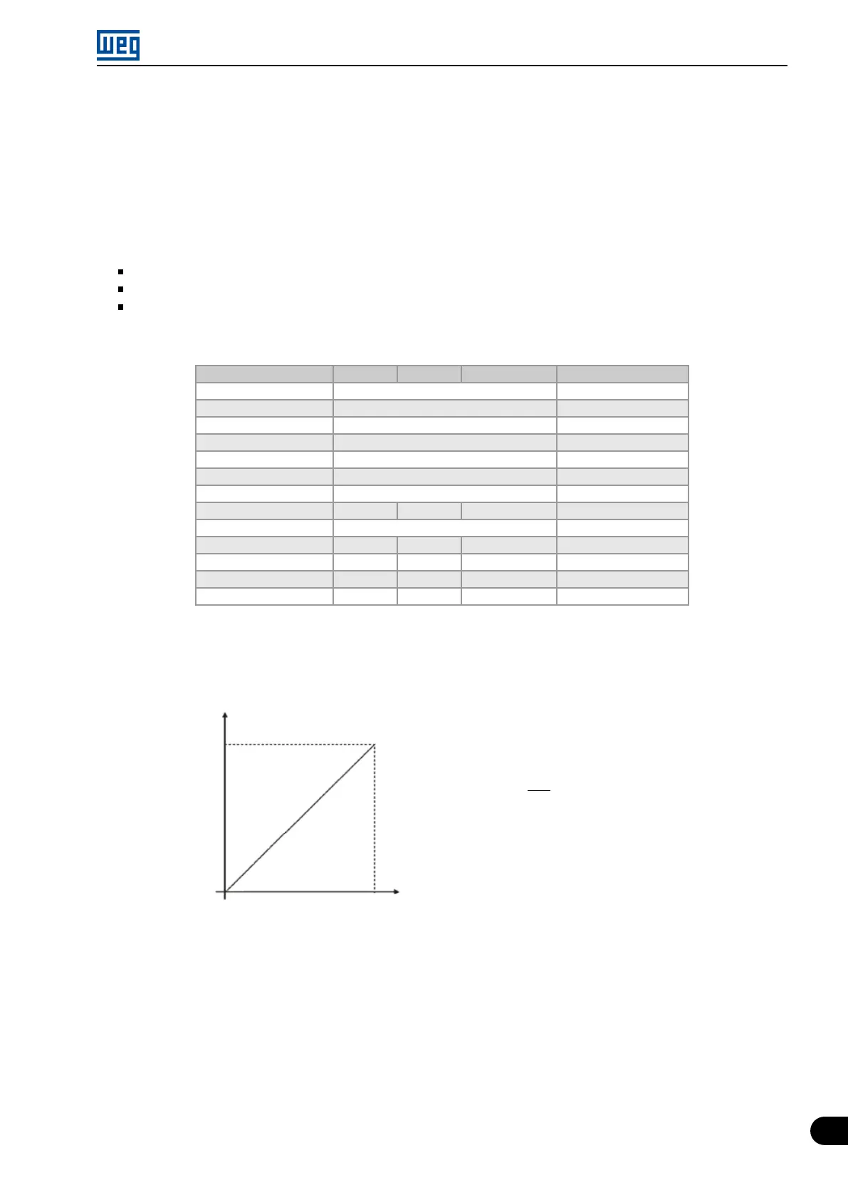
This example describes an application where the analogic input signal corresponds as frequency reference. Thus,
the total excursion of analogic signal represents the drive of the motor from its minimum frequency to its maximum
frequency, as presented on Figure 15.3 on page 15-3. In this example, maximum speed is over the nominal speed
(or fielf weakeaning speed). On Table 15.2 on page 15-3 are shown the parameters that are used to the correct
setting.
Requirements:
Motor 1 HP, 220 V, 2.9 A, 1725 rpm, 60 Hz
Min. Frequency = 0 Hz
Max. Frequency = 80 Hz
Parametrization:
Table 15.2: Parameters for application 2
Analog Input AI1 AI2 Potenciometer Value
Min. Frequency P133 0.0 Hz
Max. Frequency P134 80.0 Hz
Max. Output Voltage P142 100.0 %
Interm. Output Voltage P143 50.0 %
Field Weak. Freq. P145 60.0 Hz
Intermediate Freq. P146 30.0 Hz
Selection source P220 0
Reference source P221 = 1 P221 = 2 P221 = 3 According application*
Rotation sel. P223 0
Signal function P231 P236 P241 0
Gain P232 P237 P242 1.000
Input signal P233 P238 - According application**
Offset P234 P239 P244 0 %
(*)
Consult
Chapter 7 COMMAND AND REFERENCES on page 7-1.
(**) For AIx consult Chapter 9.1 ANALOG INPUTS on page 9-1 , for potenciometer this parameter is not available.
Example:
P134 (80 Hz)
P133 (0 Hz)
0 ....................................... 10 V
0 ....................................... 20 mA
4 ....................................... 20 mA
10 V .................................... 0
20 mA ................................. 0
20 mA ............................... 4 mA
AIx Signal
Output
frequency
For AI1 set to 0-10 V (P233=0)
and an analog input of 5 V:
P018(%) =
(
5 V
10 V
x (100.0 %) + 0.0 %
)
x 1.000 = 50.0 %
Output Freq. = P018 x P134 = 50.0 % x 80.0 Hz = 40.0 Hz
Figure 15.3: Result for application 2
Micro Mini Drives | 15-3