9
I/O
9 I/O
This chapter contains the parameters for setting the inverter inputs and outputs. This setting depends on the
accessory connected to the product.
✓
NOTE!
The inverter HMI only displays the parameters related to the resources available in the accessory
connected to the product.
9.1 ANALOG INPUTS
For example, the use of an external frequency reference is possible via the analogue inputs. The details for this
configuration are described in the following parameters.
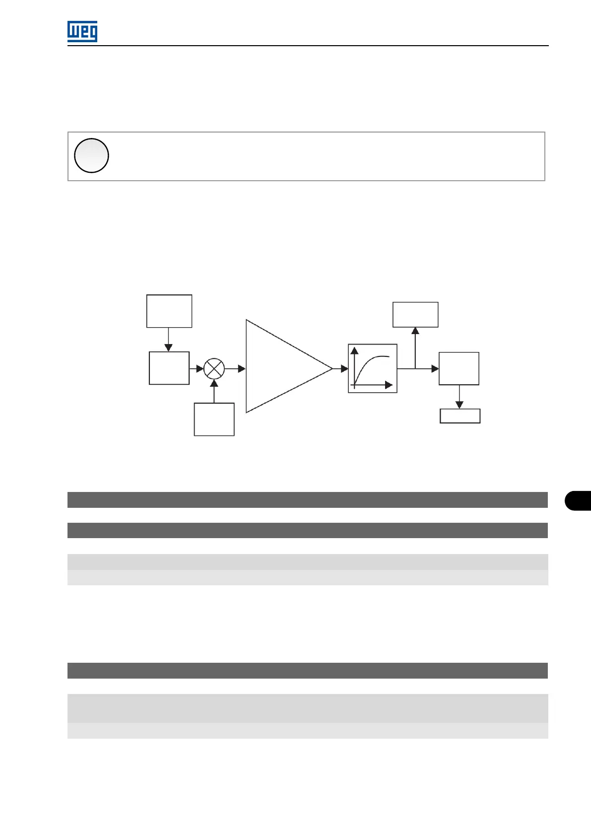
Each analog input of the inverter is defined by the steps of calculation of Signal, Offset, Gain, Filter, Function and
Value AIx, as shown in Figure 9.1 on page 9-1.
AI1 - P018
AI2 - P019
AI1 - P235
AI2 - P240
Input
AI1
AI2
(*)
Signal
AI1 - P233
AI2 - P238
Offset
AI1 - P234
AI2 - P239
Gain
AI1 - P232
AI2 - P237
Filter
Function
AI1 - P231
AI2 - P236
Value AIx
(internal)
(*) Control terminal available on the IO´s expansion accessory.
Figure 9.1: Block diagram of the analog inputs - (AIx)
P018 - AI1 Value
P019 - AI2 Value
Range: -100.0 to 100.0 %
Properties: ro
Description:
Those read-only parameters indicate the value of the analog inputs AI1 and AI2 in percentage of the full scale. The
indicated values are those obtained after the offset action and multiplication by the gain. Check the description of
parameters P230 to P245.
P230 - Dead Zone (AIs and FI1 )
Range: 0 = Inactive
1 = Active
Properties: cfg
Description:
This parameter acts for the analog inputs (AIx) or for the frequency input (FI) programmed as frequency reference,
and it defines if the dead zone in those inputs is Active (1) or Inactive (0).
If the parameter is configured as Inactive (P230 = 0), the signal in the analog inputs will actuate on the frequency
Micro Mini Drives | 9-1