9
I/O
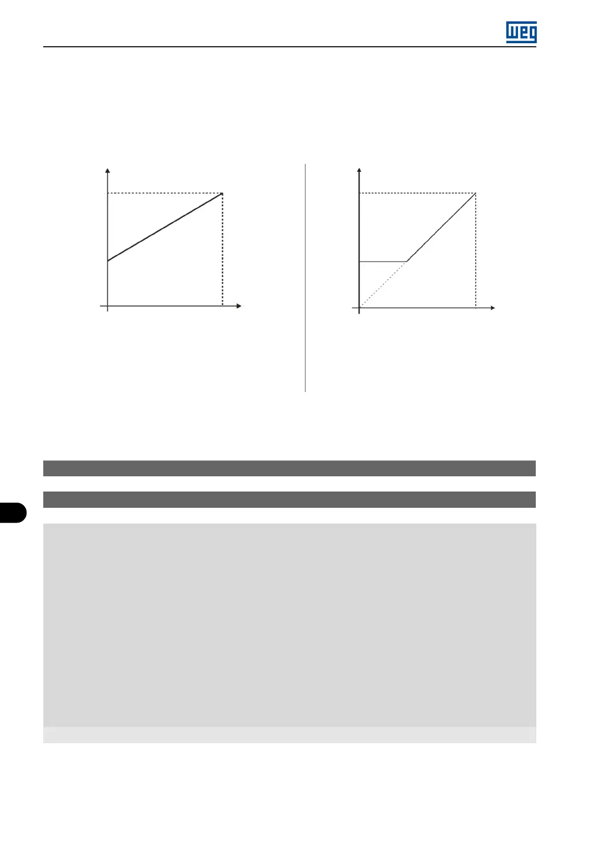
reference from the minimum point (0 V / 0 mA / 4 mA or 10 V / 20 mA), and it will be directly related to the minimum
frequency set in P133. Check Figure 9.2 on page 9-2.
If the parameter is set as Active (P230 = 1), the signal in the analog inputs will have a dead zone, where the frequency
reference remains at the Minimum frequency value (P133), even with the variation of the input signal. Check Figure
9.2 on page 9-2.
P133
P133
P134 P134
0..........................................10 V
0..........................................20 mA
4 mA...................................20 mA
10 V.......................................0
20 mA...................................0
20 mA...................................4 mA
0...........................................10 V
0...........................................20 mA
4 mA....................................20 mA
10 V.......................................0
20 mA....................................0
20 mA....................................4 mA
Signal AIx
Signal AIx
ReferenceReference
(a) Inactive (a) Active
Figure 9.2: (a) and (b) Actuation of the analog inputs with dead zone
P231 - AI1 Signal Function
P236 - AI2 Signal Function
Range: 0 = Speed Ref.
1 to 3 = Not Used
4 = PTC
5 to 6 = Not Used
7 = PLC Use
8 = Application Function 1
9 = Application Function 2
10 = Application Function 3
11 = Application Function 4
12 = Application Function 5
13 = Application Function 6
14 = Application Function 7
15 = Application Function 8
16 = Control Setpoint
17 = Process Variable
Properties: cfg
Description:
These parameters define the analog inputs functions.
When the 0 option (Speed Reference) is selected, the analog input can provide the frequency reference for the
motor, subject to the specified limits (P133 and P134) and to the action of the ramps (P100 to P103). However, it
is also necessary to configure parameters P221 and/or P222 by selecting the analog input. For further details, see
9-2 | Micro Mini Drives