4
ABOUT THE HMI
4 ABOUT THE HMI
4.1 USE OF THE HMI TO OPERATE THE INVERTER
Using the HMI, it is possible to command the inverter, view and adjust all of its parameters. The HMI presents the
following functions:
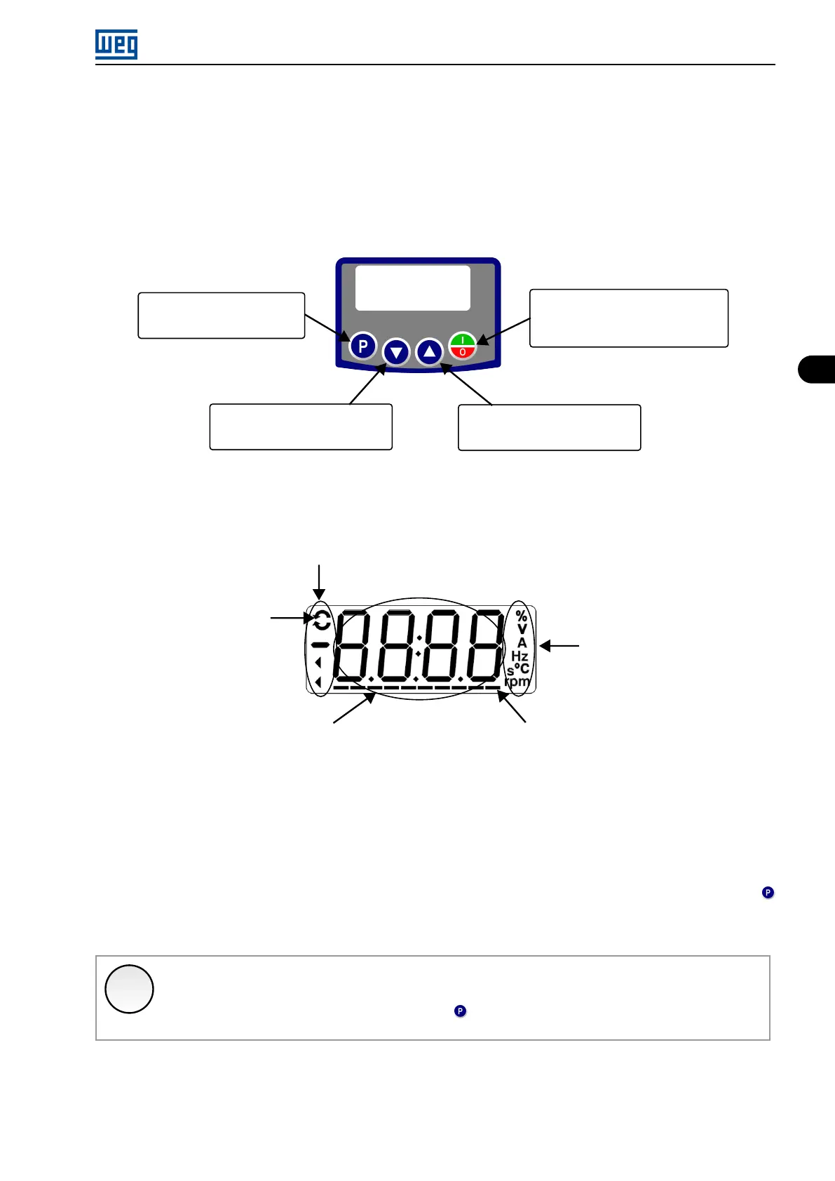
Selects (switches) between the
parameter number and its value
(position/content).
Decreases (decrements) the
frequency, parameter number or
parameter value.
Increases (increments) the
frequency, parameter number or
parameter value.
Enables/Disables the inverter via
acceleration/deceleration ramp
(start/stop, according to P229). Resets
the inverter after a fault.
Figure 4.1: HMI keys
4.2 INDICATIONS ON THE HMI DISPLAY
Inverter status
Direction of rotation
Unit of measurement
(it refers to the value
of the main display)
Bar Graph to monitor the variable
Main display
Figure 4.2: Display areas
4.3 OPERATING MODES OF THE HMI
When inverter is powered-up, the initial state of the HMI remains in the start-up mode as long as no faults, alarms,
undervoltages occur or no keys are pressed.
The setting mode is composed of two levels: Level 1 allows browsing the parameters. Level 2 allows the
modification of the parameter selected in level 1. At the end of this level, the modified value is saved when the
key is pressed.
A Figure 4.2 on page 4-1 illustrates the basic browsing of the operating modes of the HMI.
✓
NOTE!
When the inverter is in the fault state, the main display indicates the number of the fault in the format
Fxxx.The browsing is allowed after pressing the key.
Micro Mini Drives | 4-1