8
MOTOR CONTROL
Actuation: when the DC link voltage reaches the level set in P151, a command is sent to the ”ramp” block, which
inhibits the motor frequency variation according to Figure 8.12 on page 8-19 and Figure 8.20 on page 8-27.
Use recommended in the drive of loads with high moment of inertia referred to the motor shaft or loads that
require short deceleration ramps.
8.1.2.1.2 DC Link Voltage Limitation by “Accelerate Ramp” (P150 = 1 or 3)
It has effect in any situation, regardless the motor frequency condition: accelerating, decelerating or constant
frequency.
Actuation: when the DC link voltage reaches the level set in P151, a command is sent to the ramp block to
accelerate the motor.
Use recommended for the drive of loads that require braking torques at constant frequency in the inverter output.
For example, the drive of loads with eccentric shaft as in sucker rod pumps; another application is the handling
of loads with balance like in the translation in overhead cranes.
P149 - DC Link Comp. Mode
Range: 0 = Inactive
1 = Standard
2 = Overmodulation
3 = Extended
Properties: cfg, V/f
Description:
The voltage of the capacitor bank (or DC Link) originates from the voltage of the rectified supply line. The value
of this voltage varies according to the characteristics of the power line where the inverter is installed and the load
requirements of the motor driven by the inverter.
The value of the output voltage (voltage applied to the motor) is directly related to the DC Link voltage through the
modulation index. The modulation index is defined as a ratio between the fundamental component amplitude in
the inverter phase output voltage and the DC link voltage.
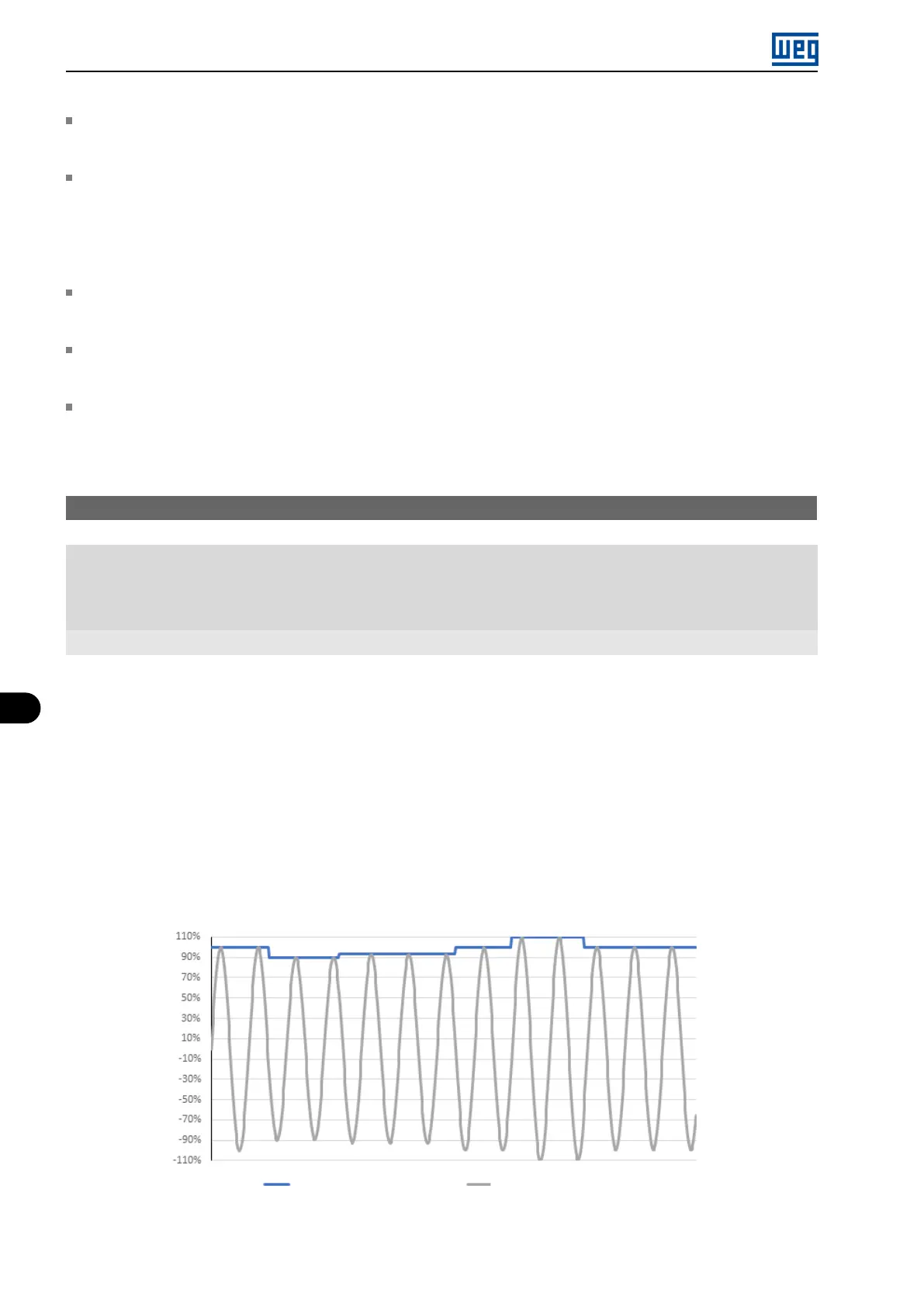
Thus, variations in the supply line voltage affect the DC Link voltage, which cause variations in the output voltage,
as shown in Figure 8.2 on page 8-4, preventing the output voltage from reaching its maximum value.
DC link voltage ( % Vdc) Output Voltage ( % Vca)
Figure 8.2: Influence of the DC Link in the output voltage
8-4 | Micro Mini Drives