8
MOTOR CONTROL
application.
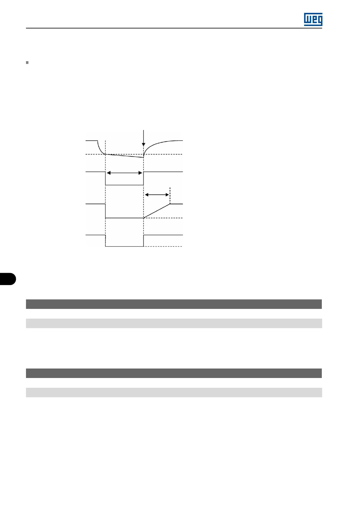
Ride-Through Function (RT): The Ride-Through function will disable the inverter output pulses (IGBT) as soon
as the supply voltage reaches a value below the undervoltage value. A fault due to undervoltage (F021) does not
occur and the DC link voltage will slowly drop until the supply voltage returns. In case it takes the supply voltage
too long to return (over 2 seconds), the inverter may indicate F021 (undervoltage on the DC link). If the supply
voltage returns before, the inverter will enable the pulses again, imposing the frequency reference instantly (like
in the Flying Start function) and making a voltage ramp with time defined by parameter P331. Refer to Figure 8.7
on page 8-10.
Return line
DC Link
voltage
Level F021
t
disab.
> t
dead
Enabled
Output pulses
P331
Output voltage
Disabled
0 V
Output
frequency (P002)
0 Hz
Figure 8.7: Actuation of the Ride-Through function
The Ride-Through function allows recovering the inverter without locking by undervoltage F021 for momentary
power supply drops. The time interval accepted during a fault is at most two seconds.
P331 - Voltage Ramp for FS and RT
Range: 0.2 to 60.0 s
Description:
This parameter determines the rising time of the output voltage during the execution of the Flying Start and Ride-
Through functions.
P332 - Dead Time
Range: 0.1 to 10.0 s
Description:
Parameter P332 sets the minimum time the frequency inverter will wait until driving the motor again with the Ride
Through function, which is necessary to demagnetize the motor.
8.1.4 DC Braking
The DC Braking allows stopping the motor by applying direct current to it. The current applied at the DC Braking is
proportional to the braking torque and may be set in P302. It is set in percentage (%) of the inverter rated current
considering the motor of power compatible with the inverter.
8-10 | Micro Mini Drives