9
I/O
P240 - AI2 Input Filter
Range: 0.00 to 16.00 s
Description:
These parameters define the times of the analog input filters.
9.2 NTC SENSOR INPUT
Depending on the inverter (see the user’s manual), there is an expansion module that has an exclusive analog input
to connect an NTC sensor. The parameter to read the temperature is described below.
P375 - NTC Temperature
Range: 0 to 200 ºC
Properties: ro
Description:
This read-only parameter indicates the temperature value obtained from the NTC sensor.
For further details, refer to the installation, configuration and operation guide of the expansion module.
✓
NOTE!
When the NTC sensor is not connected to the accessory, the frequency inverter will display 999 °C
in parameter P375. If the NTC connecting pins (accessory connector) are short-circuited, the value
indicated in P375 will be 0 °C.
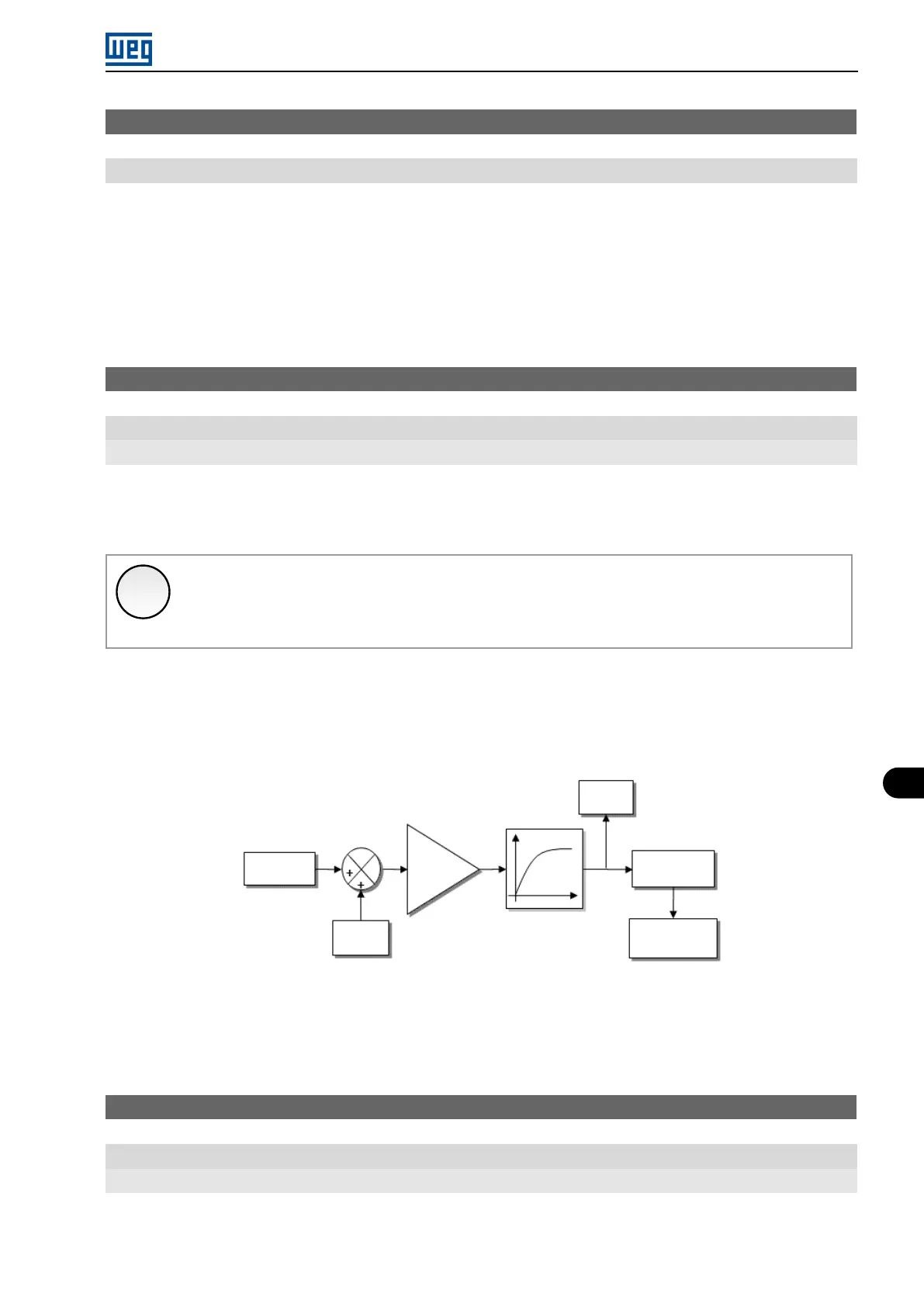
9.3 SIGNAL POTENTIOMETER INPUT
The IOP accessory provides the potentiometer signal value for the frequency inverter. The steps to calculate this
value are indicated in the block diagram of the Figure 9.3 on page 9-5.
Function
P241
Value AIP
(internal)
Offset
P244
Input
IOP
Gain
P242
P245
Filter
Value
P020
Figure 9.3: Block diagram of the AIP potentiometer signal input
The AIP value can be used as a frequency reference or accessed by the WPS software. The details for the possible
configurations are described in the following parameters.
P020 - Potentiometer Signal Value
Range: -100.0 to 100.0 %
Properties: ro
Description:
This read-only parameter indicates the analog signal value of the AIP potentiometer as a percentage of the full scale.
Micro Mini Drives | 9-5