9
I/O
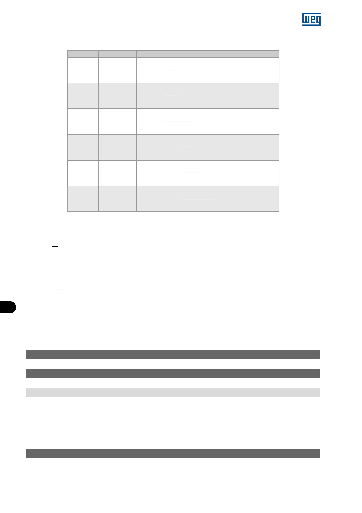
Table 9.1: Alx configuration and equation
Signal P233 or P238 Equation AIx(%)
0 to 10 V 0 AIx(%) =
(
AIx(V)
10 V
x (100,0 %) + offset
)
x gain
0 to 20 mA 0 AIx(%) =
(
AIx(mA)
20 mA
x (100,0 %) + offset
)
x gain
4 to 20 mA 1 AIx(%) =
(
AIx(mA) - 4 mA
16 mA
x (100,0 %) + offset
)
x gain
10 to 0 V 2 AIx(%) = 100 % -
(
AIx(V)
10 V
x (100,0 %) + offset
)
x gain
20 to 0 mA 2 AIx(%) = 100 % -
(
AIx(mA)
20 mA
x (100,0 %) + offset
)
x gain
20 to 4 mA 3 AIx(%) = 100 % -
(
AIx(mA) - 4 mA
16 mA
x (100,0 %) + offset
)
x gain
For example: AIx = 5 V, offset = -70.0 %, gain = 1.000, with signal of 0 to 10 V, that is, AIx
ini
= 0 and AIx
FE
= 10.
AIx(%) =
5
10
x (100.0 %) + (-70 %)
x 1.000 = -20.0 %
Another example: AIx = 12 mA, offset = -80.0 %, gain = 1.000, with signal of 4 to 20 mA, that is, AIx
ini
= 4 and
AIx
FE
= 16.
AIx(%) =
12 - 4
16
x (100.0 %) + (-80 %)
x 1.000 = -30.0 %
AIx = -30.0 % means that the motor will spin forward with a reference in module equal to 30.0 % of P134, if the
signal AIx function is ”Frequency Reference”.
In the case of filter parameters (P235), the value set corresponds to the time constant used to filter the input signal
read. Therefore, the filter response time is around three times the value of this time constant.
P234 - AI1 Input Offset
P239 - AI2 Input Offset
Range: -100.0 to 100.0 %
Description:
The parameters define the offsets of the analog inputs.
Each analog input of the inverter is defined by the steps of calculation of Signal, Offset, Gain, Filter, Function and
Value AIx, as shown in Figure 9.1 on page 9-1.
P235 - AI1 Input Filter
9-4 | Micro Mini Drives