1
QUICK REFERENCE OF ALARMS AND FAULTS
1 QUICK REFERENCE OF ALARMS AND FAULTS
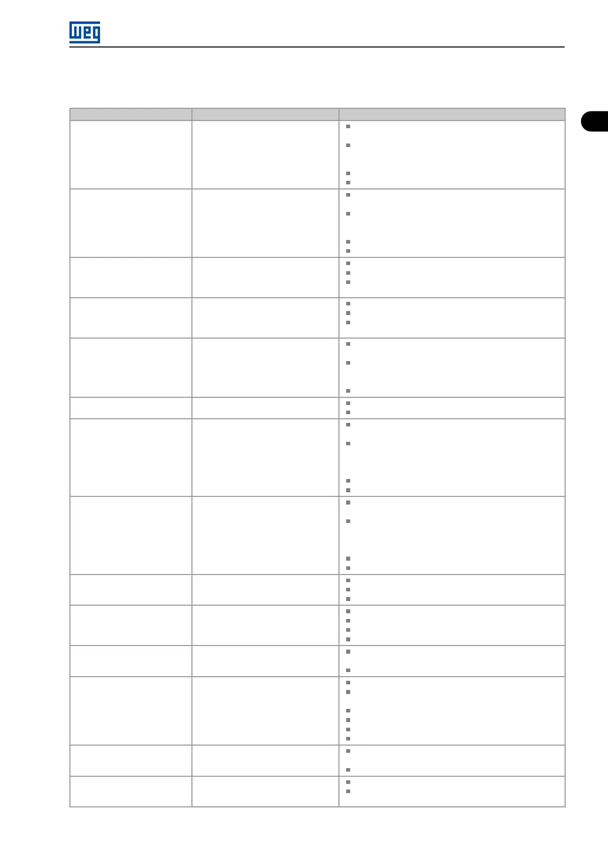
Fault / Alarm Description Possible Causes
F021
Undervoltage on the DC Link
Undervoltage fault on the intermediate
circuit.
Wrong voltage supply; check if the data on the inverter label
comply with the power supply and parameter P296.
Supply voltage too low, producing voltage on the DC Link
below the minimum value (Level F021) according to Table
10.1 on page 10-3.
Phase fault in the input.
Fault in the pre-charge circuit.
F022
Overvoltage on the DC Link
Overvoltage fault on the intermediate
circuit.
Wrong voltage supply; check if the data on the inverter label
comply with the power supply and parameter P296.
Supply voltage is too high, producing voltage on the DC
Link above the maximum value (Level F022) according to
Table 10.1 on page 10-3.
Load inertia is too high or deceleration ramp is too fast.
P151 setting is too high.
F031
Fault in Communication with
Expansion Accessory
Main control cannot establish the
communication link with the IOs
expansion accessory.
Accessory damaged.
Poor connection of the accessory.
Problem in the identification of the accessory; refer to P027.
F032
Comm. Plug-in module
comunication Lost
Main control cannot establish
the communication link with the
communication acccessory.
Accessory damaged.
Poor connection of the accessory.
Problem in the identification of the accessory; refer to P028.
F033
VVW Self-tuning Fault
Stator resistance setting fault P409. Stator resistance value in P409 does not comply with the
inverter power.
Motor connection error; turn off the power supply and
check the motor terminal box and the connections with the
motor terminals.
Motor power too low or too high in relation to the inverter.
A046
Motor Overload
Motor overload alarm. Settings of P156 is too low for the used motor.
Overload on the motor shaft.
A050
IGBTs Overtemperatures
Overtemperature alarm from the power
module temperature sensor (NTC).
High temperature at IGBTs. P030 > Level A050, according
to Table 11.1 on page 11-4.
High ambient temperature around the inverter and high
output current. For further information, refer to of the
user’s manual available for download on the website:
www.weg.net.
Blocked or defective fan.
Heatsink is too dirty, preventing the air flow.
F051
IGBTs Overtemperatures
Overtemperature fault measured on
the temperature sensor of the power
pack.
High temperature at IGBTs. P030 > Level F051, according
to Table 11.1 on page 11-4.
High ambient temperature around the inverter and high
output current. For further information, refer to of the
user’s manual available for download on the website:
www.weg.net.
Blocked or defective fan.
Heatsink is too dirty, preventing the air flow.
F067
Incorrect Encoder/ Motor
Wiring
Fault related to the phase relation of the
encoder signals.
Output motor cables U, V, W are inverted.
Encoder channels A and B are inverted.
Encoder was not properly mounted.
F070
Overcurrent/Shortcircuit
Overcurrent or short-circuit on the
output, DC Link or braking resistor.
Short-circuit between two motor phases.
IGBTs module in short-circuit or damaged.
Start with too short acceleration ramp.
Start with motor spinning without the Flying Start function.
F072
Motor Overload
Motor overload fault. P156, P157 or P158 setting is too low in relation to the
motor operating current.
Overload on the motor shaft.
F078
Motor Overtemperature
Overtemperature fault measured on
the motor temperature sensor (Triple
PTC) via analog input AIx
Overload on the motor shaft.
Load cycle is too high (high number of starts and stops per
minute).
High ambient temperature around the motor.
Poor contact or short-circuit (3k9 < R
PTC
< 0k1).
Motor thermistor not installed.
Motor shaft is stuck.
F079
Encoder Signal Fault
Fault of encoder signals absent. Wiring between encoder and interface accessory to
encoder broken.
Encoder defective.
F080
CPU Fault (Watchdog)
Fault related to the supervision
algorithm of the inverter main CPU.
Electric noise.
Inverter firmware fault.
Micro Mini Drives | 1-1